National Museum of the US Air Force
Early in July of 2006, we visited the National Museum of the US Air Force at Wright-Patterson Air Force Base near Dayton, Ohio.
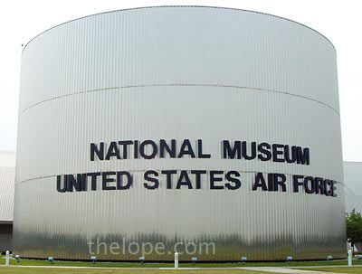
The museum is essentially a collection of aircraft, missiles, artifacts and the IMAX theater that seems to be a prerequisite for large museums these days, all held in a group of three huge hangers with connecting galleries.

The hangers are decorated with emblems from different periods of Air Force history.

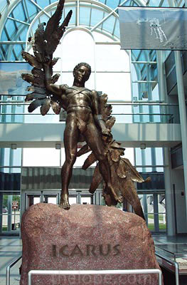
A statue of Icarus, the mythical Greek who wore wings but fell to his death because he flew too close to the sun, dominates the entry. I always wonder why we don't see more tribute paid to his father, Daedalus, who used wings wisely and lived to tell the tale.
I should state right off the bat that I know next to nothing about planes, military or otherwise. So, I have taken the measure, unusual for this blog, of simply copying the information about planes and artifacts pictured, with permission, from the museum's website. Plane and artifact names are clickable and will lead the museum website's entry on that object. Text borrowed from their website is in bold. Any text I have to add will be italic and usually below the name of the artifact, but above the first picture.
How did I pick what to photograph?
My criteria was pretty shallow; I simply took pictures of anything I found visually appealing or unusual with little regard to historical significance, except for space stuff, which I tend to favor. As his liaison, I also kept an eye out for anything stylish enough to be pictured with Ace Jackalope.
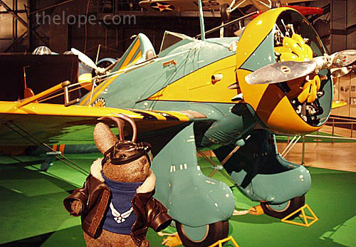
I had only intended to post a few pictures, but when I ran a recent "Where is Ace Jackalope" post that featured Ace with a Spad VII in the museum, several regular readers emailed with interest in the place. I should have anticipated that, with so many readers in Wichita KS, an aircraft industry town.
Without further ado, I present you with a feast of planes for those of you who love them, and something to merely slow down the load time for those of you who don't.
______________________
Reproduction of the 1909 Wright Military Flyer
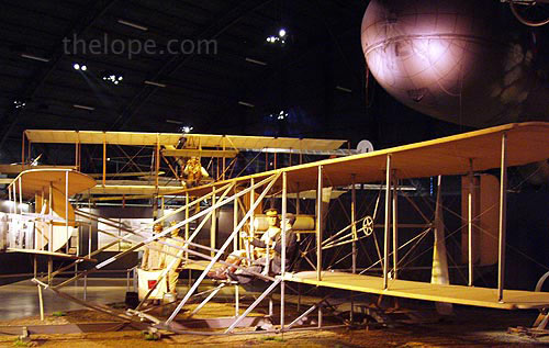
This airplane is an exact reproduction of the Wright 1909 Military Flyer. Upon being purchased by the Signal Corps for $30,000 on August 2, 1909, the original airplane was redesignated Signal Corps Airplane No. 1, the world's first military heavier-than-air flying machine. It was used in October 1909 for giving flight instructions to Lts. Frank P. Lahm and Frederic E. Humphreys, and in 1910 it was used by Lt. Benjamin D. Foulois to teach himself how to fly. By March 1911, the airplane was no longer fit for use and was retired. It is now on exhibit at the Smithsonian Institution, Washington D.C.
This reproduction was constructed in 1955 by personnel of the U.S. Air Force Museum. It is equipped with an engine donated by Mr. Orville Wright and chains, sprockets, and propellers donated by the heirs of the Wright estate.
SPECIFICATIONS
Span: 36 ft. 6 in.
Length: 28 ft. 11 in.
Height: 7 ft. 10 1/2 in.
Weight: 740 lbs.
Engine: Four cylinder Wright of 30.6 hp.
Cost: $25,000 plus $5000 bonus
PERFORMANCE
Maximum speed: 42 mph.
Maximum endurance: 1 hr. (approx.)
____________________
Reproduction of the Curtiss 1911 Model D Type IV
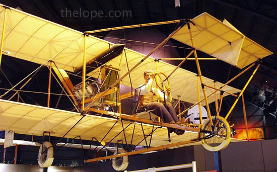
This airplane is a reproduction of the Curtiss 1911 Model D Type IV pusher, the second military airplane purchased by the U.S. Army Signal Corps. Known as Signal Corps Airplane No. 2, it was accepted at Fort Sam Houston, Texas, on April 27, 1911, one of five airplanes ordered by the Army that year. The military Model D is similar to the Curtiss Standard D pusher, having a tricycle landing gear and interplane ailerons, but the ailerons are attached to the rear instead of the front interplane struts. The wings were made in sections, making the airplane easy to disassemble and transport on Army wagons. The pilot operates the ailerons with a shoulder yoke on his seat, and the front elevator and rear rudder with the wheel mounted on a column in front of him. An observer's seat is located behind the pilot.
This reproduction was constructed in 1985-1987 by U.S. Air Force Museum personnel. They relied heavily on measurements scaled from early photographs of the original Signal Corps No. 2 because the original drawings and adequate written descriptions were not available. Additional details were gathered from an existing factory-built Curtiss pusher and from recent drawings. Except for the engine, which is made of wood and plastic, all materials used in the reproduction are essentially the same as those used in the original.
SPECIFICATIONS:
Span: 38 ft. 3 in. (including ailerons)
Length: 29 ft. 3 in.
Height: 7 ft. 10 in.
Weight: 700 lbs. empty 1,300 lbs. loaded
Engine: Curtiss V-8 of 60 hp.
Cost: $5,000
PERFORMANCE
Maximum Speed: 50 mph.
Maximum Endurance: 2 1/2 hrs. (approx)
____________________
World War I
WWI Standard J-1
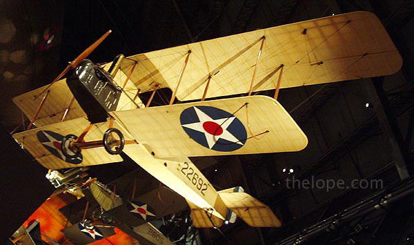
The Standard J-1 is a two-seat primary trainer developed from the earlier Sloan and Standard H-series aircraft designed by Charles Healey Day. When the U.S. entered WW I, the Army ordered the aircraft (then known as the SJ) produced as a supplement to the Curtiss Jenny then in production. At about the same time, Standard introduced an advanced version of the SJ called the JR. The Army bought only six of the JR-series aircraft, but some of the JR's features were incorporated into SJ production aircraft; the resulting version became known as the J-1.
Four companies--Standard, Dayton-Wright, Fisher Body and Wright-Martin--built 1,601 of the J-1s before production ended. Some 2,700 more J-1s on order were cancelled when the Armistice was signed. Hall-Scott engines were most commonly installed in the J-1, but some were equipped with Curtiss or Hispano-Suiza engines. Similar in appearance to the JN-4, the J-1 was said to be more difficult to fly and never gained the popularity of the legendary Jenny.
The aircraft on display was restored by Museum personnel in 1979-1981.
SPECIFICATIONS
Span: 43 ft. 10 in.
Length: 26 ft. 7 in.
Height: 10 ft. 10 In.
Weight: 2,100 lbs. loaded
Armament: None
Engine: Curtiss OXX-6 of 100 hp.
Crew: 2
Cost: $6,000
PERFORMANCE
Maximum speed: 72 mph.
Range: 235 miles (approx)
Service Ceiling: 5,800 ft.
____________________
McCook Field Wind Tunnel
I shot this because I was impressed with the woodwork, and the irony that such old word craftmanship would be used in a technological device. The light was dim and the shutter speed, long.
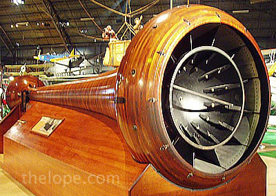
This wind tunnel was designed and built at McCook Field in 1918. Using a 24-blade fan of 60 inches diameter, the tunnel developed a maximum air speed of 453 miles per hour at its 14-inch diameter choke-throat test area.
It was used for calibrating airspeed instruments and testing airfoils. The item to be evaluated was placed in the choke-throat and viewed through the glass door. During operation, the air was drawn into the small end of the tunnel and exhausted from the large end where the fan was located.
____________________
Nieuport 28
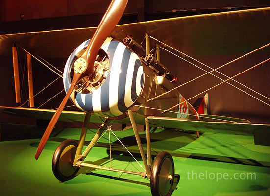
The Nieuport 28 (N.28C-1) was the first fighter airplane flown in combat by pilots of the American Expeditionary Forces (AEF) in WWI. Its second armed patrol with an AEF unit on April 14, 1918, resulted in two victories when Lts. Alan Winslow and Douglas Campbell (the first American-trained ace) of the 94th Aero Squadron each downed an enemy aircraft. Although the Nieuport 28 was considered obsolete at the time, American pilots maintained a favorable ratio of victories to losses with it. The Nieuport was more maneuverable than the sturdier SPAD XIII that replaced it, but it had a reputation for fragility and a tendency to shed its upper wing fabric in a dive. Even so, many American aces of WW I - including 26-victory ace Capt. Eddie Rickenbacker - flew the French-built Nieuport at one time or another in their careers. This reproduction was rebuilt by Museum personnel. It contains wood and hardware from an original Nieuport 28. The aircraft is painted and marked to represent a Nieuport of the 95th Aero Squadron, 3rd Flight, as it appeared in July 1918. It was placed on display in May 1994.
SPECIFICATIONS
Span: 26 ft. 3 in.
Length: 24 ft. 4 in.
Height: 8 ft.
Weight: 1,625 lbs. loaded
Armament: Two Vickers .303-cal. machine guns
Engine: Gnome 9-N rotary of 160 hp.
Crew: 1
PERFORMANCE
Maximum speed: 122 mph.
Range: 180 miles
Service Ceiling: 17,000 ft.
____________________
Fokker D.VII reproduction
The Pink Baron?
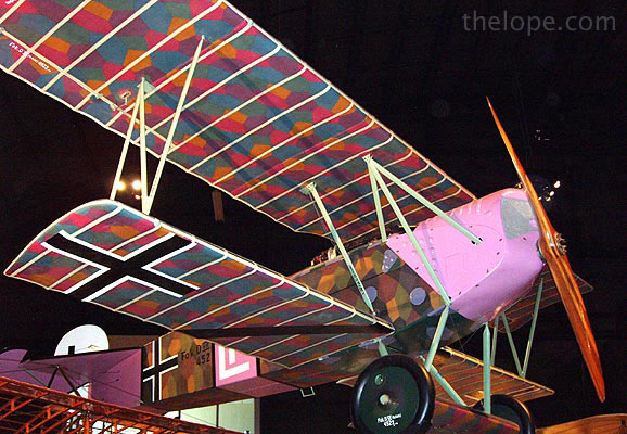
First appearing over the World War I battlefield in May 1918, the Fokker D.VII quickly showed its superior performance over Allied fighters. With its high rate of climb, higher ceiling, and excellent handling characteristics, the German pilots were able to score 565 victories over Allied aircraft during August 1918.
Designed by Reinhold Platz, the D.VII was chosen over several other designs during a competition held in January and February 1918. Baron Manfred von Richthofen, the famous Red Baron, flew the prototype, designated V11. He found it easy to fly, able to dive at high speed quickly yet remain steady as a rock, and had good visibility for the pilot. His recommendation virtually decided the competition. To achieve higher production rates, Fokker, the Albatross company, and the Allgemeine Elektrizitats Gesellschaft (A.E.G.) all built the D.VII. By war's end in November 1918, these three companies had built more than 1,700 aircraft.
The aircraft on display, a reproduction, is painted to represent the Fokker D.VII of Lt. Rudolph Stark, a squadron leader of Jasta (Fighter Squadron) 35b in October 1918. It was placed on exhibit in May 1996.
SPECIFICATIONS
Span: 29 ft. 3.5 in.
Length: 22 ft. 11.5 in.
Height: 9 ft. 2.5 in.
Weight: 1,540 lbs. empty/1,939 lbs. loaded
Armament: Two 7.92 Spandau machine guns firing through the propeller
Engine: Mercedes 160 hp. or BMW 185 hp.
Crew: One
PERFORMANCE
Max. speed: 120 mph/104 knots (Mercedes engine)/124 mph/107 knots (BMW engine)
Service ceiling: 18,000 ft. (Mercedes engine)/21,000 ft. (BMW engine)
____________________
World War I Ends, "Interwar" Years Begin
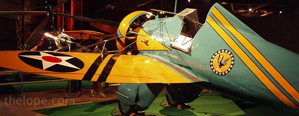
BOEING P-26A reproduction
This was my favorite plane in the whole place. I loved the body style and it's green color reminded me of a Hamilton Beech malt mixers seen at old soda fountains.
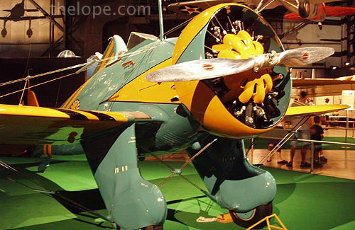
The P-26A was the first all-metal monoplane fighter (pursuit plane) produced in quantity for the U.S. Army Air Corps, affectionately called the "Peashooter" by its pilots. It was also the last Army Air Corps pursuit aircraft accepted with an open cockpit, a fixed undercarriage, and an externally braced wing. Significantly faster in level flight than previous fighters, the P-26A's relatively high landing speed caused the introduction of landing flaps to reduce this speed.
Boeing initially designed the P-26 in 1931, designating it first as Model 248 and in December 1931 as the XP-936. The company provided three test airframes, which remained Boeing property, with the frugal Air Corps providing the engines, instruments, and other equipment. The first flight occurred on March 20, 1932. The Army Air Corps purchased the three prototypes and designated them as P-26s. The Air Corps purchased a total of 111 of the production version, designating them as P-26A, and 25 of later -B and -C models.
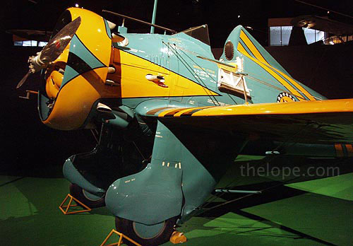
The P-26 was the Army Air Corps front-line fighter before it was replaced during 1938-40 by the Curtiss P-36A and the Seversky P-35. An export version was sold to China in 1934 where it was used against the Japanese. It was also used by the Philippine government against the Japanese in December 1941 when all were destroyed in combat.
This P-26A reproduction is painted to represent the commander's aircraft of the 19th Pursuit Squadron, 18th Pursuit Group, stationed at Wheeler Field, Hawaii, in 1938.
SPECIFICATIONS
Span: 27 ft. 11.5 in.
Length: 23 ft. 10 in.
Height: 10 ft. 5 in.
Weight: 2,197 lbs. empty/2,955 lbs. (max.)
Armament: Two fixed .30 caliber machine guns or one .50 and one .30 caliber machine gun; up to 200 lbs. of bombs
Engine: Pratt & Whitney R-1340-27 "Wasp" radial of 500 hp.
Crew: One
Cost: $16,567
PERFORMANCE
Max. speed: 234 mph/203 knots
Cruising speed: 199 mph./172 knots
Range: 360 statute miles/313 nautical miles
Service ceiling: 27,400 ft.
____________________
Link Trainer
Some of these are still in use, at least at space camps for kids and adults. I love the fact that it evolved using organ bellows.
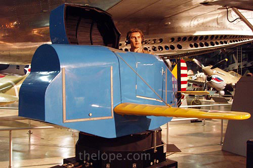
Crude pilot training aids had been designed even before WW I, but none had any significant training value. Edwin A. Link provided a giant step forward when in 1931 he received a patent on his "pilot maker" training device. He had perfected his design in the basement of his father's piano and organ factory in Binghamton, NY. Organ bellows and a motor provided the means for the trainer, mounted on a pedestal, to pitch, roll, dive and climb as the student "flew" it. Ironically, most of his first sales were to amusement parks. In 1934, after a series of tragic accidents while flying the air mail, the Army Air Corps bought six Link trainers to assist in training pilots to fly at night and in bad weather relying on instruments.
The WW II era brought orders for thousands of Link trainers from the U.S. and many foreign countries. Although Army Air Forces aviation cadets flew various trainer aircraft, virtually all took blind-flying instruction in the Link. Movement of the trainer is accomplished by vacuum operated bellows, controlled by valves connected to the control wheel (or stick) and rudder pedals. An instructor sat at the desk and transmitted radio messages which the student in the Link heard through his earphones. Inside the "cockpit", the student relied on his instruments to "fly" the Link through various maneuvers while his navigational "course" was traced on a map on the desk by the three-wheeled "crab". Slip stream simulators gave the controls the feeling of air passing over control surfaces and a rough air generator added additional realism during the "flight". The trainers were realistic enough that a humorous but unlikely story circulated that one student, told by his instructor that he had run out of fuel on a night flight, broke his ankle when he leaped from the trainer as though parachuting to safety.
The complexity of flight simulators has grown with that of military and civilian aircraft. No one knows how many lives, aircraft, and training dollars have been saved by flight simulators, but those savings can be traced back to Link's "Blue Box" which pointed the way to today's highly sophisticated and complex trainers.
______________________
MARTIN B-10
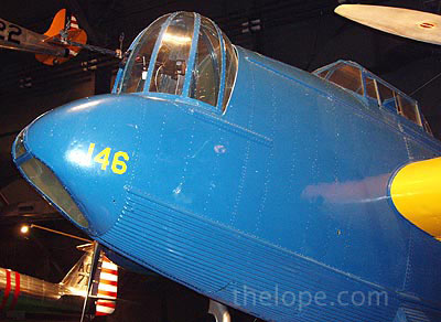
The B-10, the first of the "modern-day" all-metal monoplane bombers to be produced in quantity, featured such innovations as internal bomb storage, retractable landing gear, a rotating gun turret, and enclosed cockpits. It was so advanced in design that it was 50% faster than its contemporary biplane bombers and as fast as most of the fighters. When the Air Corps ordered 121 B-10s in the 1933-1936 period, it was the largest procurement of bomber aircraft since WW I. It also ordered 32 B-10 type bombers with Pratt and Whitney rather than Wright engines and designated these B-12s.
General Henry H. "Hap" Arnold once called the B-10 the air power wonder of its day. In 1934, he led ten B-10s on a 8,290 mile flight from Washington, D.C. to Fairbanks, Alaska and back. Although Air Corps B-10s and B-12s were replaced by B-17s and B-18s in the late 1930s, China and the Netherlands flew export versions in combat against Japan.
The aircraft on display is painted as a B-10 used in the 1934 Alaskan Flight. The only remaining B-10 known, it was an export version sold to Argentina in 1938. Donated by the Government of Argentina to the U.S. Government for the Air Force Museum in 1970, it was restored by the 96th Maintenance Squadron. (Mobile), Air Force Reserve, at Kelly AFB, Texas, in 1973-76.
SPECIFICATIONS
Span: 70 ft. 6 in.
Length: 44 ft. 9 in.
Height: 15 ft. 5 in.
Weight: 14,700 lbs. loaded
Armament: Three .30-cal. machine guns, 2,200 lbs. of bombs
Engine: Two Wright R-1820's of 775 hp. each
Cost: $55,000
PERFORMANCE
Maximum speed: 215 mph.
Cruising speed: 183 mph.
Range: 1,370 miles
Service Ceiling: 24,000 ft.
____________________
North American O-47B
I liked this one because it looks so much like the shiny toy tin airplanes of the mid 20th century. And I can just see it flying around the top of an art deco building skyscraper like the Chrysler Building.
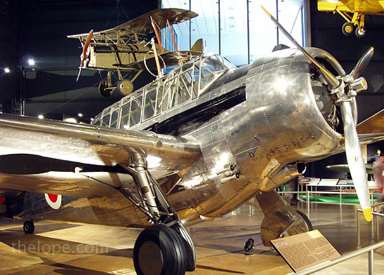
The O-47 was developed as a replacement for O-19 and O-38 observation biplanes. It was larger and heavier than most preceding observation aircraft and its crew of three sat in tandem under the long canopy. Windows in the deep belly overcame the obstacle that the wings presented to downward observation and photography. The design for the XO-47 prototype originated in 1934 with General Aviation, a subsidiary of North American Aviation, as the GA-15. The Air Corps ordered 174 O-47s in 1937-38, 93 of which were assigned to National Guard units. In 1938, the Army ordered 74 O-47Bs with a redesigned engine cowling for better cooling, a more powerful engine, and improved radio equipment.
Training maneuvers in 1941 demonstrated the shortcomings of the O-47. Light airplanes proved more capable of operating with ground troops, while fighters and twin-engine bombers showed greater ability to perform recon and photo duties. Thus, during WW II, O-47s were relegated to such duties as towing targets, coastal patrol, and anti-submarine patrol.
The O-47B on display was acquired in 1978 from Mr. Loren L. Florey, Jr., Eden Prairie, Minnesota. It was restored in the markings of an O-47A of the 112th Observation Squadron (Ohio National Guard) by the 179th Consolidated Aircraft Maintenance Squadron, Ohio ANG, at Mansfield, Ohio.
SPECIFICATIONS
Span: 46 ft. 4 in.
Length: 33 ft. 3 in.
Height: 13 ft. 9 in.
Armament: One fixed forward-firing .30-cal. machine gun and one flexible .30-cal. machine gun in rear cockpit.
Engine: Wright R-1820 of 1,060 hp.
Crew: 3
Serial number: 39-112
C/N: 51-1025
Other registrations: N73722, XB-YUW
Displayed as: 37-328
PERFORMANCE
Maximum speed: 227 mph.
Cruising speed: 200 mph.
Range: 840 miles
Service Ceiling: 24,100 ft.
_____________________
CONSOLIDATED OA-10 "CATALINA"
I like the cetacean look of the hull of this one.
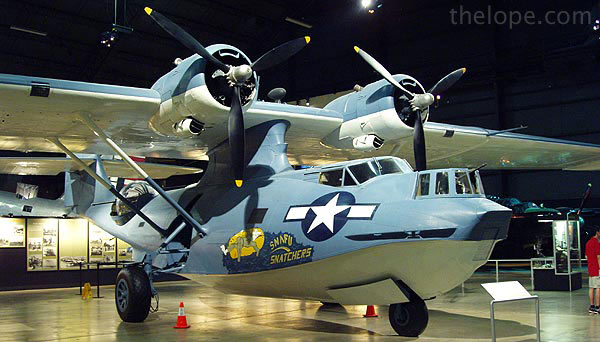
The OA-10 is the Army Air Forces version of the PBY series seaplanes and amphibians flown extensively by the Navy during WW II. It is a twin-engine, parasol-mounted monoplane equipped with a flying boat hull, retractable tricycle landing gear and retractable wing-tip floats. The OA-10 was used primarily for air-sea rescue work ("DUMBO" missions) with the AAF's Emergency Rescue Squadrons throughout WW II and for several years thereafter. During the war, OA-10 crews rescued hundreds of downed fliers.
The prototype Catalina first flew on March 28, 1935. It was produced by Consolidated Aircraft Corp. in both seaplane and amphibian versions. Catalinas were also produced by Canadian Vickers, Ltd. and the Naval Aircraft Factory. Eventually, nearly 2,500 Catalina derivatives were built for the Navy. Approximately 380 were transferred to the AAF as OA-10s, OA-10As, OA-10Bs or, in some cases, with their original Navy designations. Catalinas also were flown by a number of allied nations during and after WW II.
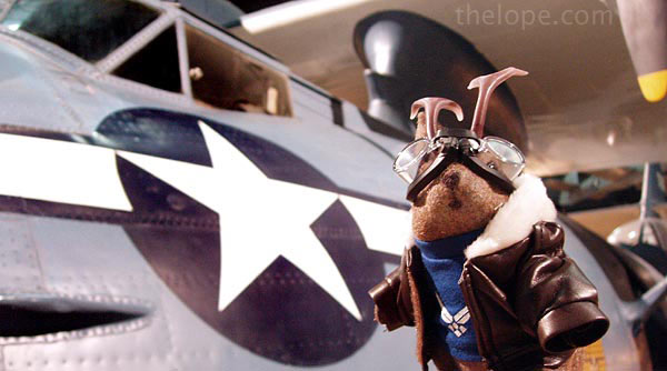
This aircraft was operated extensively by the Brazilian Air Force until 1981 in a variety of humanitarian roles in the Amazon Basin. The Catalina was flown to the Museum in 1984 and has been restored and painted as an OA-10A assigned to the 2nd Emergency Rescue Squadron which served in the Pacific Theater during WW II.
SPECIFICATIONS
Span: 104 ft.
Length: 63 ft. 10 in.
Height: 20 ft. 1 in.
Weight: 36,400 lbs. loaded
Armament: Two .50-cal. machine guns in the waist and two .30-cal. machine guns--one in the bow and another in a rear tunnel--plus 8,000 lbs. of bombs
Engines: Two Pratt & Whitney R-1830-92s of 1,200 hp ea.
Cost: $50,000
Serial Number: BuNo 46595
Other Registrations: N4583B, PT-AXM, Brazilian AF 6551
Displayed As: OA-10A 44-33879
PERFORMANCE
Maximum speed: 184 mph.
Cruising speed: 120 mph.
Range: 2,325 miles
Service Ceiling: 22,400 ft.
_____________________
BOEING B-17G "FLYING FORTRESS"
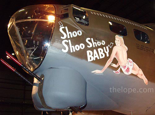
The Flying Fortress is one of the most famous airplanes ever built. The B-17 prototype first flew on July 28, 1935. Few B-17s were in service on December 7, 1941, but production quickly accelerated. The aircraft served in every WW II combat zone, but is best known for daylight strategic bombing of German industrial targets. Production ended in May 1945 and totaled 12,726.
In March 1944 this B-17G was assigned to the 91st Bomb Group--"The Ragged Irregulars"--and based at Bassingbourn, England. There it was named Shoo Shoo Baby by its crew, after a popular song. It was later renamed "Shoo Shoo Shoo Baby" after another pilot replaced the original aircraft commander. It flew 24 combat missions in WW II, receiving flak damage seven times. Its first mission (Frankfurt, Germany) was on March 24, 1944, and last mission (Posen, Poland) on May 29, 1944, when engine problems forced a landing in neutral Sweden where the airplane and crew were interned. In 1968, Shoo Shoo Baby was found abandoned in France; the French government presented the airplane to the USAF. In July 1978, the 512th Military Airlift Wing moved it to Dover AFB, Delaware, for restoration by the volunteers of the 512th Antique Restoration Group. The massive 10-year job of restoration to flying condition was completed in 1988 and the aircraft was flown to the Museum in October 1988.
SPECIFICATIONS
Span: 103 ft. 10 in.
Length: 74 ft. 4 in.
Height: 19 ft. 1 in.
Weight: 55,000 lbs. loaded
Armament: Thirteen .50-cal. machine guns with normal bomb load of 6,000 lbs.
Engines: Four Wright "Cyclone" R-1820s of 1,200 hp. ea.
Cost: $276,000
Serial Number: 42-32076
PERFORMANCE
Maximum speed: 300 mph.
Cruising speed: 170 mph.
Range: 1,850 miles
Service Ceiling: 35,000 ft.
The museum also displays the left side of the vertical tail section from B-17G 42-97683.
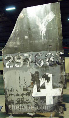
The aircraft was shot down on March 15, 1945, killing top turret gunner Technical Sergeant Sator "Sandy" Sanchez on his 66th combat mission. The tail section was discovered in 1993, being used as part of a farmer's shed near the crash site in Germany.
_____________________
World War II Begins
Some of the planes seen above were used in WWII, but they were already in development before the war.
CONSOLIDATED B-24D "LIBERATOR"
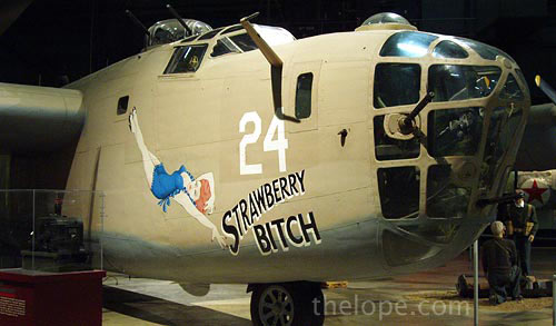
The B-24 was employed in operations in every combat theater during World War II. Because of its great range, it was particularly suited for such missions as the famous raid from North Africa against the oil industry at Ploesti, Rumania on August 1, 1943. This feature also made the airplane suitable for long over-water missions in the Pacific Theater. More than 18,000 Liberators were produced.
The B-24D on display flew combat missions from North Africa in 1943-44 with the 512th Bomb Squadron. It was flown to the U.S. Air Force Museum in May 1959. It is the same type airplane as the Lady Be Good, the world-famous B-24D which disappeared on a mission from North Africa in April 1943 and which was found in the Libyan Desert in May 1959.
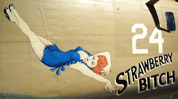
SPECIFICATIONS
Span: 110 ft. 0 in.
Length: 66 ft. 4 in.
Height: 17 ft. 11 in.
Weight: 56,000 lbs. loaded
Armament: Eleven .50-cal. machine guns [nose, left & right cheek, top turret (2), ball turret (2), left and right waist and tail (2)] plus a normal maximum load of 8,000 lbs. of bombs
Engines: Four Pratt & Whitney R-1830s of 1,200 hp. ea.
Cost: $336,000
Serial Number: 42-72843
PERFORMANCE
Maximum speed: 303 mph.
Cruising speed: 175 mph.
Range: 2,850 miles
Service Ceiling: 28,000 ft.
______________________
Intermission Cartoons
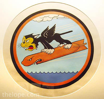
Here's an intermission for you from looking at planes. There was an exhibition of Disney-supplied artwork in support of military personnel, primarily during WWII. The exhibit was called "Disney Pins on Wings", and though a press release stated it was to run through June 11, 2006, it was still up when I was there July 3rd of that year.

This rabbit was emblematic of the 1st Ferrying Squadren.
The museum claims the exhibit is "the largest collection of original Walt Disney insignia artwork ever placed on public display", and quotes Disney Archivist, David R. Smith as saying that Disney Studio set up a special five-man crew of artists to meet the demand for the designs after they were swamped with requests from the military and war industry during World War II. By the end of the war they had created 1,200 different insignias.

Walt himself is quoted: "They meant a lot to the men who were fighting; How could you turn them down?"

Alley Oop was favored by the 327th Bomb Squadren. Unless I am mistaken, Alley Oop is not a Disney property so I may have missed some additional explanatory text on this one.
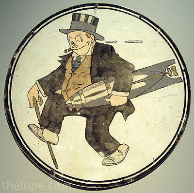
Jiggs (also not Disney, I think) has a present for someone.

During WWII, Donald Duck appeared in more than two hundred insignias; his hot temper being perfect for militant postures. Here's the ticked off duck on the nose of a B-52G s/n 58-0173 2nd bomb wing during Desert Storm.
______________________
FOCKE-ACHGELIS FA-330 "SANDPIPER"
I shot this because I didn't know such a thing had existed and thought it was interesting.
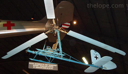
The Fa-330 Rotary Wing Kite, built in Germany during WW II, operated on the principle of the autogyro. The aircraft was designed to provide an elevated observation platform for one man while being towed behind a surfaced submarine. It was attached to the submarine by a steel cable working from a winch on the deck.
While aloft, the pilot was in contact with the submarine by telephone. In normal return to the sub, the winch wound in the cable until the Fa-330 was on the deck. There was an emergency procedure, however, by which the pilot could jettison the blades and rotor hub. When the rotor assembly separated, it automatically opened a parachute attached to both the machine and the pilot. The pilot then released his safety belt and the aircraft dropped into the sea, leaving the pilot descending alone by parachute.
The Fa-330 on display, one of very few in existence of the 200 constructed in Germany, was bought to the U.S.A. at the end of WWII.
SPECIFICATIONS
Rotor Diameter: 24 ft.
Fuselage Length: 14 ft. 7 in.
Height: 5 ft. 6 in.
Weight: 180 lbs.
Armament: None
Engine: None
PERFORMANCE
Normal towing speed: 25 mph.
Minimum towing speed: 17 mph.
Rotor speed: 205 rpm.
Max. Altitude: 720 ft. (on a 985-ft. tow cable)
______________________
DOUGLAS A-20G "HAVOC"
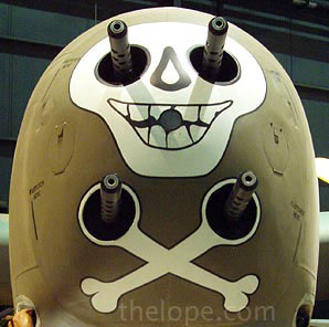
Who could resist photographing a plane with a skull on the nose?
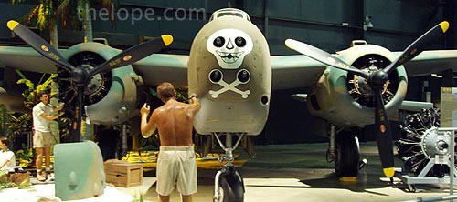
When the U.S. entered WW II, the A-20 attack bomber had already been proven in combat by British and French forces. On July 4, 1942, six A-20s flown by American crews of the 15th Bombardment Squadron accompanied six flown by British crews on a low-altitude mission against four Dutch airfields, the first U.S. daylight bombing raid in Europe.
The versatile A-20 was used in the Pacific, Middle East, North African, Russian, and European theaters. Some A-20s equipped with radar equipment and additional nose guns were redesignated as P-70s and were used as night fighters until replaced in 1944 by the P-61 "Black Widow" with its increased high altitude performance.
A-20 production halted in September 1944 with more than 7,000 built for the U.S. and its allies. The A-20G was the first series to have a "solid" nose; the aircraft on display is one of 2,850 -Gs built. It was donated by the Bankers Life and Casualty Company of Chicago in 1961, and is painted as "Little Joe" of the 5th Air Force, 312th Bomb Group, 389th Bomb Squadron.
SPECIFICATIONS
Span: 61 ft. 4 in.
Length: 48 ft.
Height: 17 ft. 7 in.
Weight: 26,580 lbs. loaded
Armament: Eight .50-cal. machine guns; 2,000 lbs. of bombs internally; 2,000 lbs. externally
Engines: Two Wright R-2600s of 1,600 hp. ea.
Cost: $74,000
Serial Number: 43-22200 (displayed as 43-21475)
C/N: 21637
PERFORMANCE
Maximum speed: 317 mph.
Cruising speed: 230 mph.
Range: 1,025 miles
Service Ceiling: 25,000 ft.
_____________________
Curtiss P-40 "Warhawk"
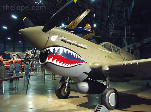
The P-40, developed from the P-36, was America's foremost fighter in service when WWII began. P-40s engaged Japanese aircraft during the attack on Pearl Harbor and the invasion of the Philippines in December 1941. They also were flown in China early in 1942 by the famed Flying Tigers and in North Africa in 1943 by the first AAF all-black unit, the 99th Fighter Squadron.
The P-40 served in numerous combat areas--the Aleutian Islands, Italy, the Middle East, the Far East, the Southwest Pacific and some were sent to Russia. Though often outclassed by its adversaries in speed, maneuverability and rate of climb, the P-40 earned a reputation in battle for extreme ruggedness. At the end of the P-40's brilliant career, more than 14,000 had been produced for service in the air forces of 28 nations, of which 2,320 were of the "E" series.
The airplane on display, a "Kittyhawk" (the export version of the P-40E built for the RAF), is painted as the P-40E flown in combat by Bruce Holloway, a pilot in both the Flying Tigers and its successor AAF unit, the 23d Fighter Group. During his tour in China, Colonel Holloway, who retired as a four star General in 1972 while the Commander of the Strategic Air Command (SAC), had a total of 13 Japanese planes to his credit.
SPECIFICATIONS
Span: 37 ft. 4 in.
Length: 31 ft. 9 in.
Height: 12 ft. 4 in.
Weight: 9,100 lbs. loaded
Armament: Six .50-cal. machine guns; 700 lbs. of bombs externally.
Engine: Allison V-1710 of 1,150 hp.
Cost: $45,000
PERFORMANCE
Maximum speed: 362 mph.
Cruising speed: 235 mph.
Range: 850 miles
Service Ceiling: 30,000 ft.
_______________________
NORTHROP P-61C "BLACK WIDOW"
This one had really cool dark blue-green paint, and it was nicely, if dimly, illuminated. But what were the Boy Scouts of America in Springfield, Ohio doing with one...merit badge for night fighting?
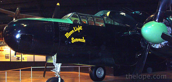
The heavily-armed Black Widow was this country's first aircraft specifically designed as a night-fighter. In the nose, it carried radar equipment which enabled its crew of two or three to locate enemy aircraft in total darkness and fly into proper position to attack.
The XP-61 was flight-tested in 1942 and delivery of production aircraft began in late 1943. The P-61 flew its first operational intercept mission as a night fighter in Europe on July 3, 1944, and later was also used as a night intruder over enemy territory. In the Pacific, a Black Widow claimed its first "kill" on the night of July 6, 1944. As P-61s became available, they replaced interim Douglas P-70s in all USAAF night fighter squadrons. During WW II, Northrop built approximately 700 P-61s; 41 of these were -Cs manufactured in the summer of 1945 offering greater speed and capable of operating at higher altitude. Northrop fabricated 36 more Black Widows in 1946 as F-15A unarmed photo-reconnaissance aircraft.
The Black Widow on display was presented to the U.S. Air Force Museum by the Tecumseh Council, Boy Scouts of America, Springfield, Ohio, in 1958. It is painted and marked as a P-61B assigned to the 550th Night Fighter Squadron serving in the Pacific in 1945.
SPECIFICATIONS
Span: 66 ft.
Length: 49 ft. 7 in.
Height: 14 ft. 8 in.
Weight: 35,855 lbs. loaded
Armament: Four .50-cal. machine guns in upper turret and four 20mm cannons in belly; 6,400 lbs. of bombs
Engines: Two Pratt & Whitney R-2800s of 2,100 hp. ea.
Cost: $170,000
Serial number: 43-8353
Displayed as: 42-39368 (P-61B)
PERFORMANCE
Maximum speed: 425 mph
Cruising speed: 275 mph
Range: 1,200 miles
Service Ceiling: 46,200 ft.
_____________________
BOEING B-29 "SUPERFORTRESS"
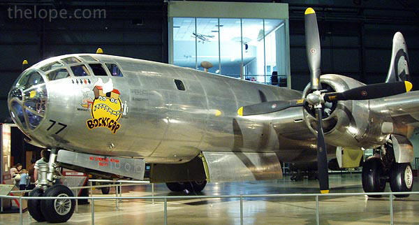
The Boeing B-29 was designed in 1940 as an eventual replacement for the B-17 and B-24. The first one built made its maiden flight on September 21, 1942. In December 1943 it was decided not to use the B-29 in the European Theater, thereby permitting the airplane to be sent to the Pacific area where its great range made it particularly suited for the long over-water flight required to attack the Japanese homeland from bases in China. During the last two months of 1944, B-29s began operating against Japan from the islands of Saipan, Guam and Tinian.
With the advent of the conflict in Korea in June 1950, the B-29 was once again thrust into battle. For the next several years it was effectively used for attacking targets in North Korea.
The B-29 on display, named "Bockscar," was flown to the U.S. Air Force Museum on September 26, 1961. It is the airplane from which the second atomic bomb was dropped on Nagasaki on August 9, 1945.
SPECIFICATIONS
Span: 141 ft. 3 in.
Length: 99 ft. 0 in.
Height: 27 ft. 9 in.
Weight: 133,500 lbs. max.
Armament: Eight or ten .50-cal. machine guns in remote controlled turrets plus two .50-cal. machine guns and one 20mm cannon in tail; 20,000 lbs. of bombs
Engines: Four Wright R-3350s of 2,200 hp. ea.
Cost: $639,000
Serial Number: 44-27297
PERFORMANCE
Maximum speed: 357 mph.
Cruising speed: 220 mph.
Range: 3,700 miles
Service Ceiling: 33,600 ft.
____________________
"Fat Man" Atomic Bomb
"It is a strange fate we should suffer so much fear and doubt over so small a thing. Such a little thing." - Boromir in J.R.R. Tolkein's Lord of the Rings
I don't know quite what to say about this except that it is very disconcerting to see an atomic bomb, the seed of a generation's nuclear nightmares, and realize it's painted like a pretty Easter egg. There was a moment of ethical awkwardness when I realized I liked the way it looked. It's also strange to realize that such a terrible thing is the genesis of so much that was aesthetically cool about the mid-20th century, such as the "atomic" look of signs like the one at Donald's Servateria. But then, someone recently wrote to me that the Air Force put the "atomic" in the "atomic age."
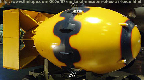
A "Fat Man" bomb was dropped over Nagasaki, Japan, on August 9, 1945 near the end of WWII. Released by the B-29 "Bockscar" on display in the USAF Museum's Air Power Gallery, the 10,000 pound weapon was detonated at an altitude of about 1,800 feet over the city. The bomb hadexplosivesive force (yield) of about 20,000 tons of TNT, about the same as the bomb dropped on Hiroshima. But because of Nagasaki's hilly terrain, the damage was somewhat less extensive than at relatively flat Hiroshima. "Fat Man" was an implosion type weapon using plutonium. A subcritical sphere of plutonium was placed in the center of a hollow sphere of high explosive (HE). Numerous detonators located on the surface of the HE were fired simultaneously to produce a powerful inward pressure on the capsule, squeezing it and increasing its density. This resulted in a supercritical condition and a nuclear explosion.
_____________________
World War II Ends, Cold War Begins
For most posts like this one, I run around taking pictures and then, sometime after the trip, I research what you are seeing so I don't post a collection of uninformative images. I must say, I found the subsequent research on this one chilling at times. I mean, I knew we were armed to the teeth and ready to rumble during the cold war - everyone knew that - but seeing so many aircraft and missiles specifically made for the purpose of man nuking man is a sobering experience.
Was it a bad thing that we were so nuke-centric? Grudgingly, I admit it was probably neccesary once the nuclear genie was uncorked.
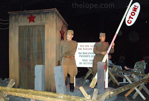
Technology is driven by politics as well as open war. At no time was this more apparent than the cold war. The museum features a small gallery on the cold war and a few exhibits.
OPERATION LITTLE VITTLES (no link available at this time; 10-10-06)

Operation Little Vittles, a symbol of American good will, was originated by a USAF airlift pilot, Lt. Gail S. Halvorsen. Impressed by the friendliness of the German youngsters outside Tempelhof airdrome, he promised to drop candy to them the next day. He did as promised and continued on succeeding days, using handkerchiefs and scraps of cloth as miniature parachutes. Word of his personal humanitarian mission spread to the U.S. and eventually donations of thousands of pounds of candy and hundreds of handkerchiefs and other pieces of scrap cloth reached him. By Jan. 1949, more than 250,000 midget parachutes with treats attached had been dropped.
When the crowds of children awaiting his C-54 grew too large for the youngster's safety, his crew dropped the candy in other sections where they saw children playing. Other candy went to schools and to children confined to Berlin hospitals. In recognition of his action and as a symbol of appreciation for the entire airlift operation, Lt. Halvorsen received the Cheney Award for 1948
...for an act of valor, extreme fortitude, or self-sacrifice in a humanitarian interest...
Ironically, Soviet propaganda attempted to discredit Halvorsen's gesture, noting that the hundreds of children had severely damaged a cemetery near tempelhof while chasing candy dropped at the site.
____________________
CONVAIR B-36J
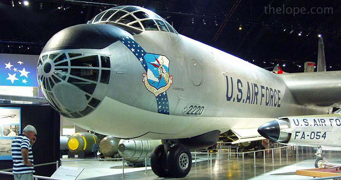
The B-36, an intercontinental bomber, was designed during WW II. The airplane made its maiden flight on August 8, 1946 and on June 26, 1948 the Strategic Air Command received its first B-36 for operational use. By August 1954, when production ended, more than 380 B-36s had been built for the USAF.
In 1958-59, the B-36 was replaced by the more modern B-52. During the years it was in service, the airplane was one of America's major deterrents to aggression by a potential enemy. The fact that the B-36 was never used in combat was indicative of its value in "keeping the peace."
The Museum's B-36J was flown to Wright Field from Davis-Monthan AFB, Arizona, on April 30, 1959. This was the last flight ever made by a B-36. It was also the first airplane to be placed inside the new Museum building.
SPECIFICATIONS
Span: 230 ft.
Length: 162 ft. 1 in.
Height: 46 ft. 9 in.
Weight: 410,000 lbs. loaded
Armament: Sixteen M24 20mm cannons in eight nose, tail and fuselage turrets; plus bombs--nuclear or 86,000 lbs. of conventional
Engines: Six Pratt & Whitney R-4360s of 3,800 hp. ea. and four General Electric J-47s of 5,200 lbs. thrust ea.
Cost: $3,701,000
Serial number: 52-2220
PERFORMANCE
Maximum speed: 435 mph.
Cruising speed: 230 mph.
Range: 10,000 miles
Service Ceiling: 45,700 ft.
______________________
DOUGLAS C-124C "GLOBEMASTER II"
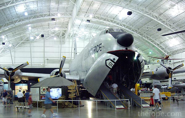
The C-124 evolved from the earlier Douglas C-74. To facilitate cargo handling, the C-124, or "Old Shakey" as it was affectionately known, featured "clamshell" loading doors and hydraulic ramps in the nose and an elevator under the aft fuselage. It was capable of handling such bulky cargo as tanks, field guns, bull dozers, and trucks. It could also be converted into a transport capable of carrying 200 fully-equipped soldiers in its double-decked cabin or 127 litter patients and their attendants.
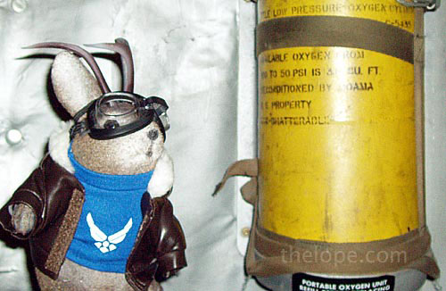
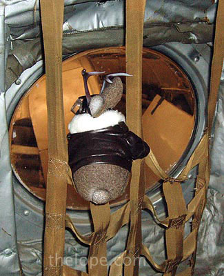
The C124C on display at the museum is open for walking in.
The first flight by a C-124 took place on Nov. 27, 1949 and deliveries of C-124As began in May 1950. The USAF bought 448 C-124s before production ended in 1955. These planes performed such missions as airlift support in the Far East and Southeast Asia, resupply missions to Antarctica, refugee evacuation in the Congo and mercy flights to Morocco, Chile and elsewhere throughout the world following floods and other natural disasters. Most C-124s were transferred to the Air Force Reserve and the Air National Guard by 1970 and all were released from active service in mid-1974.
The aircraft on display was assigned to the 165th Tactical Airlift group of the Georgia ANG following its service with the USAF. It was flown to the Museum in Aug. 1975. it is marked as a C-124 assigned to the 909th Military Airlift group making supply runs to Southeast Asia in the late 1960s and early 1970s.
SPECIFICATIONS
Span: 174 ft. 1 in.
Length: 130 ft.
Height: 48 ft. 4 in.
Weight: 216,000 lbs. max.
Armament: None
Engines: Four Pratt & Whitney R-4360s of 3,800 hp. ea.
Cost: $1,646,000
Serial Number: 52-1066
C/N: 43975
Displayed As: 51-135
PERFORMANCE
Maximum speed: 320 mph.
Cruising speed: 200 mph.
Range: 2,175 miles
Service Ceiling: 34,000 ft.
______________________
Lockheed AC-130A "Spectre" Gunship
The museum website mentions that Azreal is the angel of death in the Koran; I believe the name and concept were borrowed from Judaism. In any case, I wonder how conducive to cultural tolerance it is to use the symbol of another religion in an antagonistic manner.
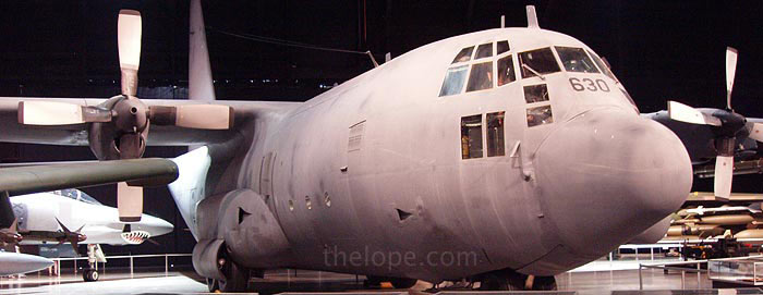
The crew of this AC-130A "Spectre" gunship, named Azrael--Angel of Death, (Azrael, in the Koran, was the angel of death who severed the soul from the body) displayed courage and heroism during the closing hours of Desert Storm. On February 26, 1991, the allied ground forces were driving the Iraqi army out of Kuwait. The crew of Azrael, Spectre #54-1630, was sent to the Al Jahra highway between Kuwait City and Basrah, Iraq, to intercept the convoys of tanks, trucks, buses, and cars that were fleeing the battle. Facing numerous enemy batteries of SA-6 and SA-8 missiles, and 37mm and 57mm radar-guided anti-aircraft artillery, the crew attacked the enemy skillfully, inflicting significant damage to the convoys. The crew's heroic efforts left much of the enemy's equipment destroyed or unserviceable, contributing to the defeat of the Iraqi forces. On February 28, 1991, Iraq agreed to a cease-fire.
During the 1950s the versatile C-130 Hercules was originally designed as an assault transport but was adapted for a variety of missions, including weather mapping and reconnaissance, mid-air space capsule recovery, search and rescue, ambulance service, drone launching, and mid-air refueling of helicopters. The C-130 could transport up to 92 combat troops and their gear or 45,000 pounds of cargo. Where facilities were inadequate, the Hercules could deliver cargo by parachute or by using the low altitude parachute extraction system (LAPES) without landing. The AC-130A "Spectre" is a C-130 that was converted to a side-firing gunship, primarily for night attacks against ground targets. In addition to its armament, it also possessed sensors, a target acquisition system, and a forward looking infra-red (FLIR) and lowlight television system.
The aircraft on display was assigned to the 919th Special Operations Wing (SOW) and was retired to the Museum in October 1995.

SPECIFICATIONS
Span: 132 ft. 7 in.
Length: 96 ft. 10 in.
Weight: 124,200 lbs. max.
Armament: Two 7.62 miniguns plus two 20mm and two 40mm cannon
Engines: Four Allison T-56-A-9D turboprops of 3,750 equivalent shaft horsepower ea.
Serial number: 54-1630
PERFORMANCE
Max. speed: 380 mph/330 knots
Cruising speed: 335 mph/291 knots
Range: 2,500 statute miles/2,172 nautical miles
Service ceiling: 33,000 ft.
(That's a McDonnell Douglas RF-4C "Phantom II" behind it.)
_____________________
Another Intermission
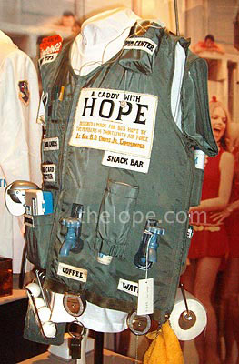
This is a golf caddy vest designed by members of the Thirteenth Air Force and presented to Bob Hope.
Hope entertained men and women of the US Air Force and the other services for more than 50 years. At least 10,000,000 U.S. soldiers benefited from his efforts through World War II, the Berlin Airlift, the Korean War, the Cold War, the Vietnam War, and more recent conflicts.
In addition to having had a Boeing C-17 named after him by the Air Force, Hope received more that 2,000 awards and citations for humanitarian and professional efforts...I bet this is the only one that dispensed golf balls and toilet paper.
______________________
Panavia Tornado GR1
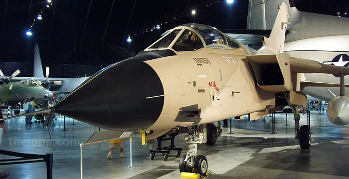
During the 1991 Gulf War, military planners made the elimination of Iraq's air defenses a top priority. At the start of OPERATION DESERT STORM (called OPERATION GRANBY by the British), Royal Air Force (RAF) Tornado GR1 aircraft attacked Iraqi air bases at low-level with Hunting JP233 anti-runway weapons and suppressed enemy air defenses. Afterward, GR1 aircrews flew medium-level missions using 1,000 lb bombs. At the end of the conflict, they used Paveway II laser-guided bombs (LGB) against other strategic targets. Flying more than 1,500 operational sorties, mostly at night, RAF GR1 aircrews played an important role in forcing the Iraqis out of Kuwait, and the RAF lost six GR1s in combat.
Development of the Tornado began in 1968, when the United Kingdom, West Germany, and Italy initiated a collaborative project to produce a low-level, supersonic aircraft. Panavia Aircraft, a new tri-national company established in Germany, built the variable sweep wing aircraft, and the first prototype flew on August 14, 1974. Operational deliveries began in July 1980.
Tornados could carry a wide range of weapons, including the Air-Launched Anti-Radar Missile (ALARM) for the Suppression of Enemy Air Defenses (SEAD) and the Paveway II and III laser-guided bombs (LGB). The RAF also modified a number of Tornados to carry the Sea Eagle anti-shipping missile. This variant became the GR1B.
The aircraft on display flew with the RAF's 17 Squadron from Dhahran, Saudi Arabia, where it sported desert camouflage and the name Miss Behavin'. The aircraft is currently painted as an aircraft assigned to the 617 Squadron. It came to the National Museum of the U. S. Air Force in October 2002 as a donation from the RAF.

TECHNICAL NOTES
Crew: Pilot and navigator in tandem seating
Armament: Two IWKA-Mauser 27 mm cannon, two AIM-9 Sidewinder missiles, and 18,000 lbs of ordnance
Engines: Two Turbo Union RB199-103 turbofans with 15,800 lbs thrust
Maximum speed: 1,452 mph at 36,000 ft
Wingspan: 45 ft 7.25 in (wings fully spread); 28 ft 2.5 in (68° sweep)
Length: 54 ft 9.5 in
_______________________
LOCKHEED F-117A "NIGHTHAWK"
Spooky...looks like something Batman would have flown in the last movie. And, no, I don't know the purpose of the protruberances on front, or why they are not symmetrical. This one was difficult to color-correct in editing, the paint seemed to pick up the varying color temperatures of lighting in odd ways.
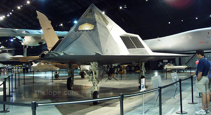
The Lockheed F-117A was developed in response to an Air Force request for an aircraft capable of attacking high value targets without being detected by hostile radar systems. By the 1970s, special materials and techniques had become available to aircraft designers that would allow them to design an aircraft with radar-evading or "stealth" qualities. The result was the F-117A, the world's first operational aircraft that fully incorporated radar-evading techniques.
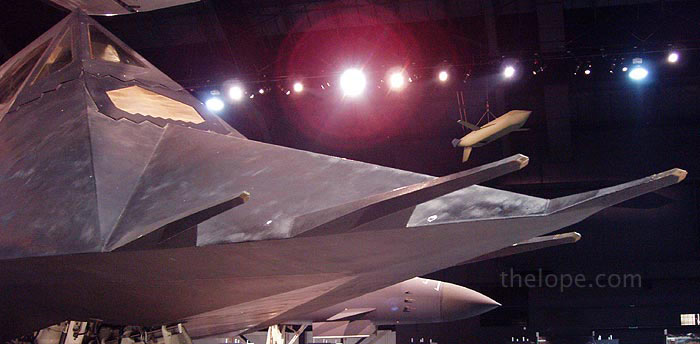
The first F-117A flew on June 18, 1981 and the first F-117A unit, the 4450th Tactical Group, achieved initial operating capability in October 1983. The 4450th was renamed the 37th Tactical Fighter Wing in October 1989. The F-117A was first used in combat during operation JUST CAUSE on December 19, 1989 when two F-117As from the 37th TFW attacked military targets in Panama. The F-117A was again called into action during Operation DESERT SHIELD/STORM in 1990-91 when the 415th and the 416th squadrons of the 37th TFW moved to a base in Saudi Arabia. During Operation DESERT STORM the F-117As flew 1,271 sorties, achieving an 80 percent mission success rate while suffering no losses or battle damage. A total of 64 F-117As were built between 1981 and 1990, 5 for testing and 59 for operational use. The F-117A was awarded the 1989 Collier Trophy, one of the most prized aeronautical awards in the world.
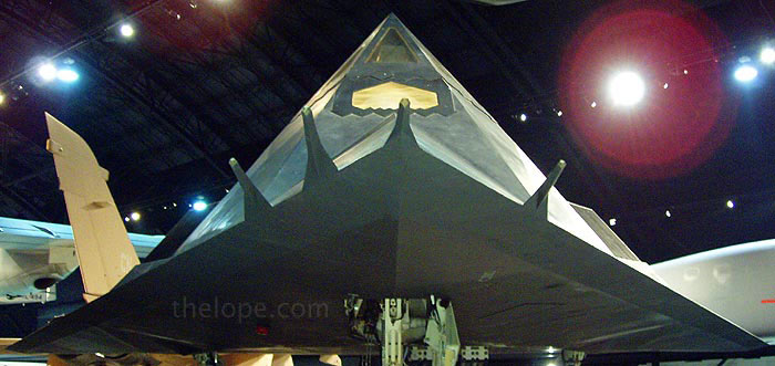
The aircraft on display is the second F-117A built and was specially modified and instrumented to test various systems. After its test program was completed, the Air Force decided to retire the aircraft in 1991. It was then turned over to the USAF Museum and is marked as it appeared during its tests conducted for the Air Force Systems Command between 1981 and 1991.
SPECIFICATIONS
Span: 43 ft. 4 in.
Length: 65 ft. 11 in.
Height: 12 ft. 5 in.
Weight: 52,500 lbs. max.
Armament: Up to 4,000 lbs. of internal stores
Engines: Two General Electric F404-F1D2 engines of 10,600 lbs. thrust ea.
Crew: One
Cost: $42,600,000
PERFORMANCE
Maximum speed: High subsonic
Cruising speed: 684 mph.
Range: Unlimited with aerial refueling
Service Ceiling: 45,000 ft.
______________________
Northrop Grumman B-2 "Spirit"
They had a nice sense of lighting design for this one; I've noticed it is used in many articles about the museum and I see why...headline grabbing "stealth" plus dramatic spotlights.
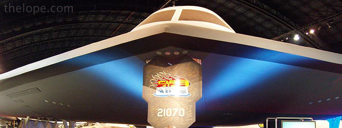
The global spread of sophisticated air defense systems in the 1980s threatened the US Air Force's ability to destroy an enemy's most valued targets. To overcome this threat, the USAF incorporated the revolutionary low-observable, or "stealth," technology into a long-range bomber capable of delivering large payloads of conventional or nuclear weapons. The Northrop Grumman B-2 Spirit merged the high aerodynamic efficiency of the "flying wing" design with composite materials, special coatings, and classified stealth technologies. As a result, the B-2 became virtually invisible to even the most sophisticated air defense radar systems.
The public first saw the highly classified B-2 on November 22, 1988, when it rolled out of its hangar at Air Force Plant 42 in Palmdale, California. The B-2 first flew on July 17, 1989, at Edwards AFB, California, and Northrop Grumman delivered the first operational B-2 on December 17, 1993. Based at Whiteman AFB, Missouri, the B-2 soon demonstrated its combat capabilities in OPERATION ALLIED FORCE over Serbia in 1999, OPERATION ENDURING FREEDOM over Afghanistan in 2001, and OPERATION IRAQI FREEDOM over Iraq in 2003. With a crew of only two, the pilot in the left seat and the mission commander in the right, a typical combat mission consisted of a non-stop flight from Whiteman AFB to the target and back. During these missions, normally lasting more than 30 hours and requiring numerous aerial refuelings, each B-2 delivered up to 40,000 lbs of precision weapons.
Structural Testing
Northrop Grumman constructed two additional aircraft without engines or instruments for fatigue testing. On the second of those test aircraft (the B-2 on display) engineers attached computer-controlled, hydraulically driven plates along the airframe to simulate all flying conditions. They calculated that the structure would reach 150 percent of the design specifications, but the wing withstood stresses over 161 percent before it finally cracked.
Early production B-2s also underwent extensive environmental testing. In 1993, the Spirit of Ohio (serial number 82-1070) endured over 1,000 hours of extensive temperature testing at the McKinley Climatic Laboratory at Eglin AFB, Florida. It withstood temperatures ranging from -65 to 120 degrees Fahrenheit, rain, and high humidity. To verify the test results outside the laboratory, the Spirit of Ohio deployed to Eielson AFB, Alaska, in March 1996 for further cold climate testing. To signify these tests, the technicians painted the "Fire and Ice" artwork on the nose landing gear panel and signed it. Given to the USAF Museum in 1999, that nose panel was installed on the Museum's B-2 during restoration.
Technical Notes
Engines: Four General Electric F118-GE-100 turbofans of 17,300 lbs thrust each
Wingspan: 172 ft
Length: 69 ft
Height: 17 ft
Speed: High subsonic
Takeoff Weight: 336,500 lbs
_____________________
Cold War Ends

The museum has this nice chunk of the Berlin Wall. Many of the planes shown above were used well after the fall of the USSR, hence the mentions of them in conjuction with the Gulf War, etc., but they were all developed before the end of the cold war. Some continue to be utilized.
_____________________
Spaceflight
Woo Hoo...Finally! I mean, some of those planes were aesthetically interesting, but few things can compete with space stuff.
"STARGAZER" GONDOLA
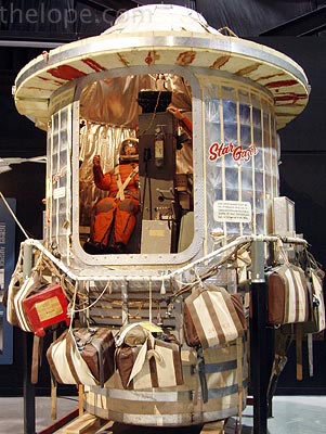
Project "Stargazer" was established in January 1959 for high-altitude astronomical investigation from above 95 percent of the Earth's atmosphere permitting undistorted visual and photographic observations of the stars and planets. On December 13-14, 1962, Captain Joseph Kittinger and Mr. William White made a flight to an altitude of 82,000 feet over New Mexico in the Stargazer gondola. In addition to obtaining valuable telescopic observations above the dense atmosphere of the earth, the flight provided valuable information relative to the development of pressure suits and associated life support systems during an extended period on the edge of space.
The balloon which supported the Stargazer capsule was a 280 foot diameter sphere of mylar film. However, at launch only a comparatively small bubble of helium gas occupied the top of the balloon with the remainder of the balloon envelope dangling beneath. As the balloon rose ever higher, the gas expanded filling the balloon until at maximum altitude, it completely filled and reshaped the envelope into a sphere. The gondola was supported below the balloon on a cable giving a total height at takeoff of some 400 feet.
____________________
PROJECT EXCELSIOR
I had never heard about this: "Kittinger fell for 4 minutes, 36 seconds. He experienced temperatures as low as minus 94 degrees Fahrenheit and a maximum speed of 714 miles per hour, exceeding the speed of sound." Read on...
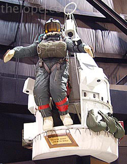
As new jet aircraft flew higher and faster in the 1950s, the Air Force became increasingly concerned with the hazards faced by flight crews ejecting from these high performance aircraft. The emerging space age introduced the problem of how to provide astronauts with a safe method of escape while within the atmosphere. Without proper stabilization, a crewmember ejecting from an aerospace vehicle at high altitudes could enter a life-threatening flat spin of up to 200 revolutions per minute. Project Excelsior, with then-Captain Joseph W. Kittinger, Jr. as test director, was established in 1958 to study and solve these high altitude escape problems. Francis Beaupre, a technician at Wright Field working on the Excelsior project, devised a parachute system that would safely enable pilots to eject from high altitudes. His system, the "Beaupre Multi-Stage Parachute," consisted of a stabilizer parachute that would prevent uncontrolled spinning and tumbling at high altitudes. A timing and altitude system automatically deployed both the stabilizing and main parachutes at the appropriate moments to ensure the safe and controlled descent of the pilot or astronaut.
As Project Excelsior did not have the resources to use high performance aircraft to test the new escape system, a balloon gondola was designed and built by the skilled staff at Wright Field to carry the pilot to the desired altitudes for the tests. The balloon held nearly 3 million cubic feet of helium to lift the open gondola high into the stratosphere. Captain Kittinger made three high altitude parachute jumps from the gondola using the Beaupre-designed parachute system. On November 16, 1959, Captain Kittinger made the first jump from Excelsior I at an altitude of 76,400 feet. During Excelsior II, the second test on December 11, 1959, Kittinger jumped from an altitude of 74,700 feet. On the third and last jump in Excelsior III on August 16, 1960, Captain Kittinger jumped from a height of 102,800 feet, almost 20 miles above the earth. With only the small stabilizing chute deployed, Kittinger fell for 4 minutes, 36 seconds. He experienced temperatures as low as minus 94 degrees Fahrenheit and a maximum speed of 714 miles per hour, exceeding the speed of sound. The 28-foot main parachute did not open until Kittinger reached the much thicker atmosphere at 17,500 feet. Kittinger safely landed in the New Mexico desert after a 13 minute 45 second descent. Project Excelsior successfully proved the new parachute system would solve the problem of high altitude escape by crewmen.
____________________
Dyna-Soar (X-20) Hypersonic Wind Tunnel Test Model
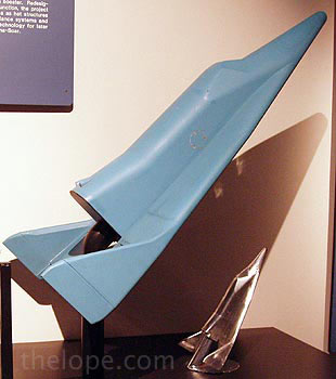
A smaller version of the large blue model also on display at the USAF Museum, this model was tested at very high airspeeds to determine reentry and hypersonic flight characteristics. A great deal of data useful in Space Shuttle and National Aerospace Plane development was acquired from tests on this and similar models during the lifetime of the Dyna-Soar X-20A project, 1957-1963.
____________________
McDONNELL MERCURY SPACECRAFT
I never tire of looking at early manned space capsules. These are the stuff of many a 1960s childhood dream. How many of you sat inside a cardboard box and listened to the countdown in your head?
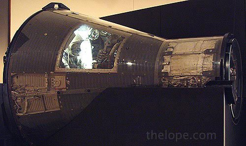
Project Mercury involved six one-man flights (1961-63) to investigate man's ability to perform in space and to test basic space technology and hardware. The Mercury capsule weighs about 2,000 pounds and is nine feet tall. The pilot reclined on a couch contoured to his individual shape. During re-entry into the Earth's atmosphere, the capsule's blunt curved end was the leading face; it was coated with heat-resistant plastics which burned away (ablated) to protect the crew compartment from excessive heating.
The spacecraft on display was flight-rated but never flown. It was used to provide parts to support the last Mercury mission, flown by Astronaut L. Gordon Cooper, Jr. on May 15-16, 1963. (On loan from the National Air and Space Museum, Smithsonian Institution.)
_____________________
McDONNELL GEMINI SPACECRAFT
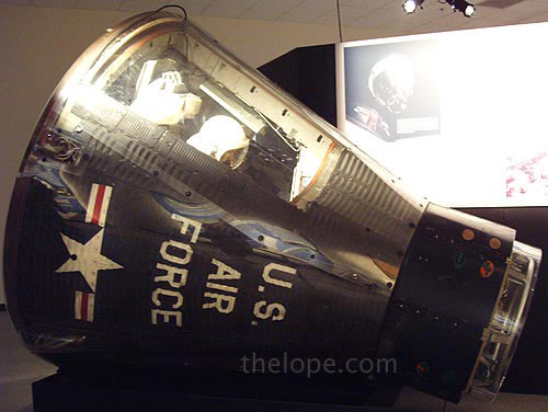
Project Gemini, which used a two-man spacecraft, bridged the gap between the Mercury program, the first tentative steps into space, and the Apollo program, which landed men on the moon. Gemini's primary objectives were to investigate the problems of long-duration spaceflight, to develop techniques for rendezvous and docking with target vehicles, and to conduct extravehicular operations. After two unmanned test flights in 1964, ten manned Gemini missions took place in 1965-66. Two of these, Gemini 6 and 7, were simultaneous so that the capsules could rendezvous in space and orbit in close formation.
The Gemini capsule weighs approximately 4,500 pounds and is 8 feet, 6 inches tall. The spacecraft on display, although flight-rated, was never flown, but was used for thermal qualification testing. (On loan from the National Air and Space Museum, Smithsonian Institution.)
______________________
North American Rockwell Apollo 15 Command Module
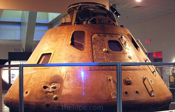
At 9:34 AM EDT on July 26, 1971, a giant Saturn V launch vehicle lifted off its launch pad at Kennedy Space Center, Florida carrying the Apollo 15 spacecraft. Aboard the command module were Col. David R. Scott, commander; Lt. Col. James B. Irwin, lunar module pilot; and Maj. Alfred M. Worden, Jr., command module pilot, comprising the first all-USAF Apollo crew. On July 30, the lunar module "Falcon," named for the USAF Academy mascot, carried astronauts Scott and Irwin to the moon's surface where they spent almost 67 hours while Astronaut Worden remained aboard the command module conducting scientific experiments and photographing lunar landmarks. At 4:46 PM EDT on August 7, the command module splashed down in the Pacific Ocean 333 miles north of Hawaii, concluding the 12-day mission. Apollo 15 was the ninth manned Apollo flight and the fourth lunar landing.
Three major components of the Apollo spacecraft were a service module containing support and propulsion systems; the lunar module, a "space taxi" to carry two astronauts to and from the moon's surface; and the command module which served as control center and living quarters for the three-man crew. The latter was the only portion of the spacecraft intended to return to Earth. The Apollo 15 command module, nicknamed "Endeavour" after the ship which carried Capt. James Cook on his 18th century scientific voyages, is 10 feet 7 inches high and weighed about 13,000 pounds at launch. Its outer shell of stainless steel honeycomb is covered with ablative or heat-dissipating material, the inner shell is aluminum honeycomb. The heat-shield on the base is made of a form of plastic (phenolic epoxy resin) which protected the crew from the 3000 degree Fahrenheit temperatures encountered during re-entry into the earth's atmosphere. The hatch on the side provided entry into the capsule while a hatch on top was used when docked with the lunar module. The command module was designed, developed, and produced by North American Rockwell Corp.
______________________
MARQUARDT SPACE SLED
This was one of my favorite things in the whole museum. The website's description mentions a mannequin in a space suit; there isn't one right now as all of the space suits have been temporarily removed during a renovation.
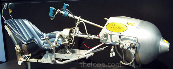
And I love the almost googie sticker on what I assume is the sled's motor.

A design for individual space maneuvering in the vicinity of a space craft, the space sled lost out to the seat-like maneuvering unit. The Mannequin riding the sled is wearing an experimental space suit which was one of a series tested in the mid-1960s. Unlike the space sled, the suit was part of a continuing evolution which produced the operational space suits used today.
____________________
The following are two items which were not on display at the time of my visit; I am told by museum personnel that they should be back on display by April 2007, or so. I am using their pictures with permission and listing them because of the number of space aficionados who read this blog...and because they look sci-fi cool!
Litton Suit - 1958
I love this one. I'd seen a Litton hard suit, which looks like a cross between a suit of armor and a space suit, but had never seen this older, softer version. I bet it was the inspiration for a few B-movie space suits as well as some sci-fi book cover art.
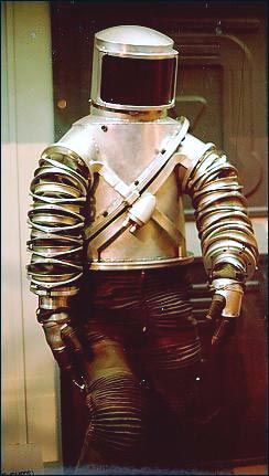
This USAF Mark I Extravehicular and Lunar Surface Suit, designed and built by Litton Industries, predated both the launch of Sputnik I by the Soviet Union and the creation of the National Aeronautics and Space Administration (NASA) by the United States. Based on a Litton "constant-volume" concept of the so-called "hard suit" of early 1955, the Mark I was tested during the 1958-59 period for more than 600 hours at simulated altitudes exceeding 100 miles. The unique construction of this suit permitted almost a full range of body motions by the person wearing it. The great success of the Mark I led to the subsequent development of a more refined and satisfactory RX-series "Moon Suits" for NASA.
On June 9, 1958 Captain Iven C. Kincheloe Jr., a famous USAF test pilot, tested the Mark I in a simulated flight to 100 miles and found it completely satisfactory.
_____________________
INTEGRATED MANEUVERING
LIFE SUPPORT SYSTEM, 1969
This is the way kids of the 50s and 60s imagined astronauts would jet around in space - not the bulky seat-like Manned Maneuvering Unit (MMU) they ultimately used.
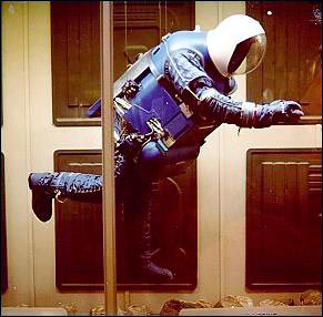
I cannot find a link to the museum's site for this one, but here is the description they had at a former link:
The Integrated Maneuvering Life Support System (IMLSS) was essentially a small free-flying spacecraft. It was designed by United Aircraft's Hamilton Standard Division for use aboard the U.S. Air Force's Manned Orbiting Laboratory (MOL, 1963-69). IMLSS featured propulsion and life support independent of the MOL space station, but it could also operate connected to the MOL via an umbilical. The Department of Defense canceled the MOL project before protective outer thermal garments for this unit were created. IMLSS experience contributed to NASA's current Shuttle Extravehicular Mobility Unit.
_____________________
Missiles
These are the missiles in the Missile and Space Gallery. This shot is the only one that required me to use my old 35mm camera; I needed the 20mm ultra-wide lens.
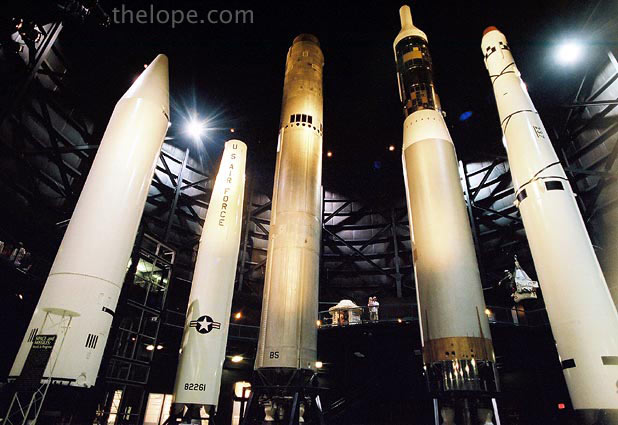
Left end:
Chrysler PGM-19 "Jupiter"
The Jupiter intermediate range ballistic missile (IRBM) was developed by the Army's Ballistic Missile Agency at the Redstone Arsenal, Alabama, under Dr. Wernher von Braun. However, in 1956 the Department of Defense limited the Army's operational employment of missiles to those with less than a 200-mile range and when the Jupiter became operational in 1959, it was placed under USAF control.
Originally designed as the SM-78, the Jupiter was a single-stage, liquid-propellant missile using an all-inertial guidance system to direct it toward the target. The first test launch of a Jupiter occurred on March 1, 1957 and two months later, during the third test, a Jupiter achieved its design range of 1,500 miles. Jupiter squadrons of 15 missiles each were deployed at NATO launch sites in Italy and Turkey in 1961; training for USAF and NATO personnel was carried out at Redstone Arsenal.
Production of Jupiter IRBMs was completed in December 1960. As more advanced missiles were developed, the Jupiter became out-dated and in 1963 it was withdrawn from military use. Some modified versions of the Jupiter were used as first stage boosters to launch various U.S. space satellites. The Air Force Museum's Jupiter was obtained from the Chrysler Corporation in 1963.
SPECIFICATIONS
Length: 65 ft. 4 in.
Diameter: 8 ft. 9 in.
Weight: 109,000 lbs. at launch
Armament: Nuclear warhead
Engine: North American Rocketdyne S-3D liquid rocket engine of 150,000 lbs. thrust
Cost: $735,000
PERFORMANCE
Max. speed: 11,500 mph. / 9,993 knots
Max. range: 1,500 statute miles / 1,303 nautical miles
Max. altitude: 410 statute miles / 356 nautical miles
Second from left:
DOUGLAS PGM-17 "THOR"
The single-stage Thor intermediate range ballistic missile (IRBM) originally designated as the SM-75, entered active military service in September 1958, thus becoming the free world's first operational IRBM. The first Thor missile was delivered to Cape Canaveral, Florida, for testing less than a year after the development contract was signed. The Thor was launched from a combination transporter-erector vehicle and was directed to its target by a self-contained inertial guidance system.
Thor missiles were assigned to the Strategic Air Command and were also deployed to England early in 1959 where they were maintained in a state of combat-readiness by the Royal Air Force. With the development of more advanced missiles, the Thor was retired from its military role in 1963. However, some Thor missiles were modified and used extensively for space research, either as a single-stage booster or in combination with various types of upper stages for such projects as the Tiros, Telstar, Pioneer, and Discoverer programs.
The Air Force Museum's Thor missile was delivered from Vandenberg AFB, California in 1963.
SPECIFICATIONS
Length: 64 ft. 10 in.
Diameter: 8 ft. 0 in.
Weight: 109,330 lbs. at launch
Armament: Nuclear warhead
Engine: North American Rocketdyne S-3 liquid-propellant rocket engine of 150,000 lbs. thrust
Cost: $660,000
PERFORMANCE
Max. speed: 10,250 mph. / 8,907 knots
Max. range: 1,725 statute miles / 1,499 nautical miles
Max. altitude: 390 statute miles / 339 nautical miles
There's no entry on the museum's website for the middle missile, but it's a Martin SM-68 "Titan II" intercontinental ballistic missile, designed to carry nuclear warheads. If you're a child of the space race, you may remember it for a more peaceful purpose - the launch vehicle that carried the Gemini spacecraft. I once got to see one of these lifted out of a missile silo slated for destruction as part of the SALT II treaty with the Soviet Union.
Fourth from left:
MARTIN HGM-25A "TITAN I"
The two-stage Titan I, together with the Atlas, comprised our nation's first generation of liquid-fueled, strategic, intercontinental ballistic missiles (ICBMs). Operational Titan Is contained an all-inertial guidance system to direct the nuclear warhead to the target. Liquid propellants for the Titan I's Aerojet rocket engines were kerosene fuel and liquid oxygen. The HGM-25A, formerly known as the SM-68 (or B-68), was the first USAF ICBM to be placed in hardened underground silos for protection against enemy attack. However, they had to be lifted from their silos to the surface by elevator prior to launching.
The USAF launched its first test Titan I on February 6, 1959 and in April 1962, the first Strategic Air Command squadron of nine Titan I's was declared operational. Eventually squadrons of Titan I's were deployed at five different bases in the western U.S. By 1965, however, Titan I's were being phased out in favor of Titan II's which offer greater range and payload, and are launched from within their silos. Modified Titan II's also were used to launch the Gemini astronauts into space. The larger and more versatile Titan III, developed from the Titan II, is one of the Air Force's major launch vehicles for its many military space programs.
SPECIFICATIONS
Length: 98 ft. 4 in.
Diameter: 10 ft. 0 in.
Weight: 221,500 lbs. at launch
Armament: Nuclear warhead
Engines: Two Aerojet-General liquid propellant boosters; an LR87 first stage engine of 430,000 lbs. thrust and a second stage of 80,000 lbs. thrust
Cost: $1,502,000
PERFORMANCE
Max. speed: 15,000 mph. / 13,904 knots
Max. range: 6,300 statute miles / 5,475 nautical miles
Max. altitude: 620 statute miles / 538 nautical miles
Far right:
Thor Agena A
The US Air Force launched the world’s first space photo reconnaissance satellites using a rocket like the Thor Agena A on display. These satellites, secretly code-named Corona, took pictures of the Soviet Union’s bomber and missile bases during the Cold War. The USAF and the Central Intelligence Agency jointly managed Corona, which was known to the public as the Discoverer research satellite program.
Launch System
The Thor Agena A launch vehicle combined a Thor ballistic missile (similar to the nuclear-armed version on display in the Missile & Space Gallery, but designated SLV-2 or Space Launch Vehicle-2), with an Agena upper stage. At first, the Agena vehicle was meant to be carried atop Atlas boosters, but the 1957 Soviet launch of Sputnik—the first satellite—sped up the US Discoverer program. Thor was the first vehicle available to carry Agenas.
Originally, Thor was designed as an intermediate-range nuclear ballistic missile (IRBM) in 1956. It borrowed engine and guidance technology from the developing Atlas program, and Thor IRBMs were operational in Great Britain from 1959 to 1963. Though Thor was created quickly as an interim nuclear deterrent, it later became a very successful satellite launch vehicle. The long-lived Delta rocket series, based on refinements of the original Thor design, operated through the end of the Cold War and beyond.
For those of you wondering how much time it takes to see the indoor parts of the place, these pictures span exactly 2 1/2 hours and I was rushing by the time I got to the space stuff. There are also exhibits outside, but we didn't manage to see those.
The National Museum of the US Air Force is located at:
1100 Spaatz St.
Wright-Patterson AFB, OH 45433
The phone number at the time of this writing is (937) 255-3286

The museum is essentially a collection of aircraft, missiles, artifacts and the IMAX theater that seems to be a prerequisite for large museums these days, all held in a group of three huge hangers with connecting galleries.

The hangers are decorated with emblems from different periods of Air Force history.

A statue of Icarus, the mythical Greek who wore wings but fell to his death because he flew too close to the sun, dominates the entry. I always wonder why we don't see more tribute paid to his father, Daedalus, who used wings wisely and lived to tell the tale.

I should state right off the bat that I know next to nothing about planes, military or otherwise. So, I have taken the measure, unusual for this blog, of simply copying the information about planes and artifacts pictured, with permission, from the museum's website. Plane and artifact names are clickable and will lead the museum website's entry on that object. Text borrowed from their website is in bold. Any text I have to add will be italic and usually below the name of the artifact, but above the first picture.
How did I pick what to photograph?
My criteria was pretty shallow; I simply took pictures of anything I found visually appealing or unusual with little regard to historical significance, except for space stuff, which I tend to favor. As his liaison, I also kept an eye out for anything stylish enough to be pictured with Ace Jackalope.

I had only intended to post a few pictures, but when I ran a recent "Where is Ace Jackalope" post that featured Ace with a Spad VII in the museum, several regular readers emailed with interest in the place. I should have anticipated that, with so many readers in Wichita KS, an aircraft industry town.
Without further ado, I present you with a feast of planes for those of you who love them, and something to merely slow down the load time for those of you who don't.
______________________
Reproduction of the 1909 Wright Military Flyer

This airplane is an exact reproduction of the Wright 1909 Military Flyer. Upon being purchased by the Signal Corps for $30,000 on August 2, 1909, the original airplane was redesignated Signal Corps Airplane No. 1, the world's first military heavier-than-air flying machine. It was used in October 1909 for giving flight instructions to Lts. Frank P. Lahm and Frederic E. Humphreys, and in 1910 it was used by Lt. Benjamin D. Foulois to teach himself how to fly. By March 1911, the airplane was no longer fit for use and was retired. It is now on exhibit at the Smithsonian Institution, Washington D.C.
This reproduction was constructed in 1955 by personnel of the U.S. Air Force Museum. It is equipped with an engine donated by Mr. Orville Wright and chains, sprockets, and propellers donated by the heirs of the Wright estate.
SPECIFICATIONS
Span: 36 ft. 6 in.
Length: 28 ft. 11 in.
Height: 7 ft. 10 1/2 in.
Weight: 740 lbs.
Engine: Four cylinder Wright of 30.6 hp.
Cost: $25,000 plus $5000 bonus
PERFORMANCE
Maximum speed: 42 mph.
Maximum endurance: 1 hr. (approx.)
____________________
Reproduction of the Curtiss 1911 Model D Type IV

This airplane is a reproduction of the Curtiss 1911 Model D Type IV pusher, the second military airplane purchased by the U.S. Army Signal Corps. Known as Signal Corps Airplane No. 2, it was accepted at Fort Sam Houston, Texas, on April 27, 1911, one of five airplanes ordered by the Army that year. The military Model D is similar to the Curtiss Standard D pusher, having a tricycle landing gear and interplane ailerons, but the ailerons are attached to the rear instead of the front interplane struts. The wings were made in sections, making the airplane easy to disassemble and transport on Army wagons. The pilot operates the ailerons with a shoulder yoke on his seat, and the front elevator and rear rudder with the wheel mounted on a column in front of him. An observer's seat is located behind the pilot.
This reproduction was constructed in 1985-1987 by U.S. Air Force Museum personnel. They relied heavily on measurements scaled from early photographs of the original Signal Corps No. 2 because the original drawings and adequate written descriptions were not available. Additional details were gathered from an existing factory-built Curtiss pusher and from recent drawings. Except for the engine, which is made of wood and plastic, all materials used in the reproduction are essentially the same as those used in the original.
SPECIFICATIONS:
Span: 38 ft. 3 in. (including ailerons)
Length: 29 ft. 3 in.
Height: 7 ft. 10 in.
Weight: 700 lbs. empty 1,300 lbs. loaded
Engine: Curtiss V-8 of 60 hp.
Cost: $5,000
PERFORMANCE
Maximum Speed: 50 mph.
Maximum Endurance: 2 1/2 hrs. (approx)
____________________
World War I
WWI Standard J-1

The Standard J-1 is a two-seat primary trainer developed from the earlier Sloan and Standard H-series aircraft designed by Charles Healey Day. When the U.S. entered WW I, the Army ordered the aircraft (then known as the SJ) produced as a supplement to the Curtiss Jenny then in production. At about the same time, Standard introduced an advanced version of the SJ called the JR. The Army bought only six of the JR-series aircraft, but some of the JR's features were incorporated into SJ production aircraft; the resulting version became known as the J-1.
Four companies--Standard, Dayton-Wright, Fisher Body and Wright-Martin--built 1,601 of the J-1s before production ended. Some 2,700 more J-1s on order were cancelled when the Armistice was signed. Hall-Scott engines were most commonly installed in the J-1, but some were equipped with Curtiss or Hispano-Suiza engines. Similar in appearance to the JN-4, the J-1 was said to be more difficult to fly and never gained the popularity of the legendary Jenny.
The aircraft on display was restored by Museum personnel in 1979-1981.
SPECIFICATIONS
Span: 43 ft. 10 in.
Length: 26 ft. 7 in.
Height: 10 ft. 10 In.
Weight: 2,100 lbs. loaded
Armament: None
Engine: Curtiss OXX-6 of 100 hp.
Crew: 2
Cost: $6,000
PERFORMANCE
Maximum speed: 72 mph.
Range: 235 miles (approx)
Service Ceiling: 5,800 ft.
____________________
McCook Field Wind Tunnel
I shot this because I was impressed with the woodwork, and the irony that such old word craftmanship would be used in a technological device. The light was dim and the shutter speed, long.

This wind tunnel was designed and built at McCook Field in 1918. Using a 24-blade fan of 60 inches diameter, the tunnel developed a maximum air speed of 453 miles per hour at its 14-inch diameter choke-throat test area.
It was used for calibrating airspeed instruments and testing airfoils. The item to be evaluated was placed in the choke-throat and viewed through the glass door. During operation, the air was drawn into the small end of the tunnel and exhausted from the large end where the fan was located.
____________________
Nieuport 28

The Nieuport 28 (N.28C-1) was the first fighter airplane flown in combat by pilots of the American Expeditionary Forces (AEF) in WWI. Its second armed patrol with an AEF unit on April 14, 1918, resulted in two victories when Lts. Alan Winslow and Douglas Campbell (the first American-trained ace) of the 94th Aero Squadron each downed an enemy aircraft. Although the Nieuport 28 was considered obsolete at the time, American pilots maintained a favorable ratio of victories to losses with it. The Nieuport was more maneuverable than the sturdier SPAD XIII that replaced it, but it had a reputation for fragility and a tendency to shed its upper wing fabric in a dive. Even so, many American aces of WW I - including 26-victory ace Capt. Eddie Rickenbacker - flew the French-built Nieuport at one time or another in their careers. This reproduction was rebuilt by Museum personnel. It contains wood and hardware from an original Nieuport 28. The aircraft is painted and marked to represent a Nieuport of the 95th Aero Squadron, 3rd Flight, as it appeared in July 1918. It was placed on display in May 1994.
SPECIFICATIONS
Span: 26 ft. 3 in.
Length: 24 ft. 4 in.
Height: 8 ft.
Weight: 1,625 lbs. loaded
Armament: Two Vickers .303-cal. machine guns
Engine: Gnome 9-N rotary of 160 hp.
Crew: 1
PERFORMANCE
Maximum speed: 122 mph.
Range: 180 miles
Service Ceiling: 17,000 ft.
____________________
Fokker D.VII reproduction
The Pink Baron?

First appearing over the World War I battlefield in May 1918, the Fokker D.VII quickly showed its superior performance over Allied fighters. With its high rate of climb, higher ceiling, and excellent handling characteristics, the German pilots were able to score 565 victories over Allied aircraft during August 1918.
Designed by Reinhold Platz, the D.VII was chosen over several other designs during a competition held in January and February 1918. Baron Manfred von Richthofen, the famous Red Baron, flew the prototype, designated V11. He found it easy to fly, able to dive at high speed quickly yet remain steady as a rock, and had good visibility for the pilot. His recommendation virtually decided the competition. To achieve higher production rates, Fokker, the Albatross company, and the Allgemeine Elektrizitats Gesellschaft (A.E.G.) all built the D.VII. By war's end in November 1918, these three companies had built more than 1,700 aircraft.
The aircraft on display, a reproduction, is painted to represent the Fokker D.VII of Lt. Rudolph Stark, a squadron leader of Jasta (Fighter Squadron) 35b in October 1918. It was placed on exhibit in May 1996.
SPECIFICATIONS
Span: 29 ft. 3.5 in.
Length: 22 ft. 11.5 in.
Height: 9 ft. 2.5 in.
Weight: 1,540 lbs. empty/1,939 lbs. loaded
Armament: Two 7.92 Spandau machine guns firing through the propeller
Engine: Mercedes 160 hp. or BMW 185 hp.
Crew: One
PERFORMANCE
Max. speed: 120 mph/104 knots (Mercedes engine)/124 mph/107 knots (BMW engine)
Service ceiling: 18,000 ft. (Mercedes engine)/21,000 ft. (BMW engine)
____________________
World War I Ends, "Interwar" Years Begin
BOEING P-26A reproduction
This was my favorite plane in the whole place. I loved the body style and it's green color reminded me of a Hamilton Beech malt mixers seen at old soda fountains.

The P-26A was the first all-metal monoplane fighter (pursuit plane) produced in quantity for the U.S. Army Air Corps, affectionately called the "Peashooter" by its pilots. It was also the last Army Air Corps pursuit aircraft accepted with an open cockpit, a fixed undercarriage, and an externally braced wing. Significantly faster in level flight than previous fighters, the P-26A's relatively high landing speed caused the introduction of landing flaps to reduce this speed.
Boeing initially designed the P-26 in 1931, designating it first as Model 248 and in December 1931 as the XP-936. The company provided three test airframes, which remained Boeing property, with the frugal Air Corps providing the engines, instruments, and other equipment. The first flight occurred on March 20, 1932. The Army Air Corps purchased the three prototypes and designated them as P-26s. The Air Corps purchased a total of 111 of the production version, designating them as P-26A, and 25 of later -B and -C models.

The P-26 was the Army Air Corps front-line fighter before it was replaced during 1938-40 by the Curtiss P-36A and the Seversky P-35. An export version was sold to China in 1934 where it was used against the Japanese. It was also used by the Philippine government against the Japanese in December 1941 when all were destroyed in combat.
This P-26A reproduction is painted to represent the commander's aircraft of the 19th Pursuit Squadron, 18th Pursuit Group, stationed at Wheeler Field, Hawaii, in 1938.

SPECIFICATIONS
Span: 27 ft. 11.5 in.
Length: 23 ft. 10 in.
Height: 10 ft. 5 in.
Weight: 2,197 lbs. empty/2,955 lbs. (max.)
Armament: Two fixed .30 caliber machine guns or one .50 and one .30 caliber machine gun; up to 200 lbs. of bombs
Engine: Pratt & Whitney R-1340-27 "Wasp" radial of 500 hp.
Crew: One
Cost: $16,567
PERFORMANCE
Max. speed: 234 mph/203 knots
Cruising speed: 199 mph./172 knots
Range: 360 statute miles/313 nautical miles
Service ceiling: 27,400 ft.
____________________
Link Trainer
Some of these are still in use, at least at space camps for kids and adults. I love the fact that it evolved using organ bellows.

Crude pilot training aids had been designed even before WW I, but none had any significant training value. Edwin A. Link provided a giant step forward when in 1931 he received a patent on his "pilot maker" training device. He had perfected his design in the basement of his father's piano and organ factory in Binghamton, NY. Organ bellows and a motor provided the means for the trainer, mounted on a pedestal, to pitch, roll, dive and climb as the student "flew" it. Ironically, most of his first sales were to amusement parks. In 1934, after a series of tragic accidents while flying the air mail, the Army Air Corps bought six Link trainers to assist in training pilots to fly at night and in bad weather relying on instruments.
The WW II era brought orders for thousands of Link trainers from the U.S. and many foreign countries. Although Army Air Forces aviation cadets flew various trainer aircraft, virtually all took blind-flying instruction in the Link. Movement of the trainer is accomplished by vacuum operated bellows, controlled by valves connected to the control wheel (or stick) and rudder pedals. An instructor sat at the desk and transmitted radio messages which the student in the Link heard through his earphones. Inside the "cockpit", the student relied on his instruments to "fly" the Link through various maneuvers while his navigational "course" was traced on a map on the desk by the three-wheeled "crab". Slip stream simulators gave the controls the feeling of air passing over control surfaces and a rough air generator added additional realism during the "flight". The trainers were realistic enough that a humorous but unlikely story circulated that one student, told by his instructor that he had run out of fuel on a night flight, broke his ankle when he leaped from the trainer as though parachuting to safety.
The complexity of flight simulators has grown with that of military and civilian aircraft. No one knows how many lives, aircraft, and training dollars have been saved by flight simulators, but those savings can be traced back to Link's "Blue Box" which pointed the way to today's highly sophisticated and complex trainers.
______________________
MARTIN B-10

The B-10, the first of the "modern-day" all-metal monoplane bombers to be produced in quantity, featured such innovations as internal bomb storage, retractable landing gear, a rotating gun turret, and enclosed cockpits. It was so advanced in design that it was 50% faster than its contemporary biplane bombers and as fast as most of the fighters. When the Air Corps ordered 121 B-10s in the 1933-1936 period, it was the largest procurement of bomber aircraft since WW I. It also ordered 32 B-10 type bombers with Pratt and Whitney rather than Wright engines and designated these B-12s.
General Henry H. "Hap" Arnold once called the B-10 the air power wonder of its day. In 1934, he led ten B-10s on a 8,290 mile flight from Washington, D.C. to Fairbanks, Alaska and back. Although Air Corps B-10s and B-12s were replaced by B-17s and B-18s in the late 1930s, China and the Netherlands flew export versions in combat against Japan.
The aircraft on display is painted as a B-10 used in the 1934 Alaskan Flight. The only remaining B-10 known, it was an export version sold to Argentina in 1938. Donated by the Government of Argentina to the U.S. Government for the Air Force Museum in 1970, it was restored by the 96th Maintenance Squadron. (Mobile), Air Force Reserve, at Kelly AFB, Texas, in 1973-76.
SPECIFICATIONS
Span: 70 ft. 6 in.
Length: 44 ft. 9 in.
Height: 15 ft. 5 in.
Weight: 14,700 lbs. loaded
Armament: Three .30-cal. machine guns, 2,200 lbs. of bombs
Engine: Two Wright R-1820's of 775 hp. each
Cost: $55,000
PERFORMANCE
Maximum speed: 215 mph.
Cruising speed: 183 mph.
Range: 1,370 miles
Service Ceiling: 24,000 ft.
____________________
North American O-47B
I liked this one because it looks so much like the shiny toy tin airplanes of the mid 20th century. And I can just see it flying around the top of an art deco building skyscraper like the Chrysler Building.

The O-47 was developed as a replacement for O-19 and O-38 observation biplanes. It was larger and heavier than most preceding observation aircraft and its crew of three sat in tandem under the long canopy. Windows in the deep belly overcame the obstacle that the wings presented to downward observation and photography. The design for the XO-47 prototype originated in 1934 with General Aviation, a subsidiary of North American Aviation, as the GA-15. The Air Corps ordered 174 O-47s in 1937-38, 93 of which were assigned to National Guard units. In 1938, the Army ordered 74 O-47Bs with a redesigned engine cowling for better cooling, a more powerful engine, and improved radio equipment.
Training maneuvers in 1941 demonstrated the shortcomings of the O-47. Light airplanes proved more capable of operating with ground troops, while fighters and twin-engine bombers showed greater ability to perform recon and photo duties. Thus, during WW II, O-47s were relegated to such duties as towing targets, coastal patrol, and anti-submarine patrol.
The O-47B on display was acquired in 1978 from Mr. Loren L. Florey, Jr., Eden Prairie, Minnesota. It was restored in the markings of an O-47A of the 112th Observation Squadron (Ohio National Guard) by the 179th Consolidated Aircraft Maintenance Squadron, Ohio ANG, at Mansfield, Ohio.
SPECIFICATIONS
Span: 46 ft. 4 in.
Length: 33 ft. 3 in.
Height: 13 ft. 9 in.
Armament: One fixed forward-firing .30-cal. machine gun and one flexible .30-cal. machine gun in rear cockpit.
Engine: Wright R-1820 of 1,060 hp.
Crew: 3
Serial number: 39-112
C/N: 51-1025
Other registrations: N73722, XB-YUW
Displayed as: 37-328
PERFORMANCE
Maximum speed: 227 mph.
Cruising speed: 200 mph.
Range: 840 miles
Service Ceiling: 24,100 ft.
_____________________
CONSOLIDATED OA-10 "CATALINA"
I like the cetacean look of the hull of this one.

The OA-10 is the Army Air Forces version of the PBY series seaplanes and amphibians flown extensively by the Navy during WW II. It is a twin-engine, parasol-mounted monoplane equipped with a flying boat hull, retractable tricycle landing gear and retractable wing-tip floats. The OA-10 was used primarily for air-sea rescue work ("DUMBO" missions) with the AAF's Emergency Rescue Squadrons throughout WW II and for several years thereafter. During the war, OA-10 crews rescued hundreds of downed fliers.
The prototype Catalina first flew on March 28, 1935. It was produced by Consolidated Aircraft Corp. in both seaplane and amphibian versions. Catalinas were also produced by Canadian Vickers, Ltd. and the Naval Aircraft Factory. Eventually, nearly 2,500 Catalina derivatives were built for the Navy. Approximately 380 were transferred to the AAF as OA-10s, OA-10As, OA-10Bs or, in some cases, with their original Navy designations. Catalinas also were flown by a number of allied nations during and after WW II.

This aircraft was operated extensively by the Brazilian Air Force until 1981 in a variety of humanitarian roles in the Amazon Basin. The Catalina was flown to the Museum in 1984 and has been restored and painted as an OA-10A assigned to the 2nd Emergency Rescue Squadron which served in the Pacific Theater during WW II.
SPECIFICATIONS
Span: 104 ft.
Length: 63 ft. 10 in.
Height: 20 ft. 1 in.
Weight: 36,400 lbs. loaded
Armament: Two .50-cal. machine guns in the waist and two .30-cal. machine guns--one in the bow and another in a rear tunnel--plus 8,000 lbs. of bombs
Engines: Two Pratt & Whitney R-1830-92s of 1,200 hp ea.
Cost: $50,000
Serial Number: BuNo 46595
Other Registrations: N4583B, PT-AXM, Brazilian AF 6551
Displayed As: OA-10A 44-33879
PERFORMANCE
Maximum speed: 184 mph.
Cruising speed: 120 mph.
Range: 2,325 miles
Service Ceiling: 22,400 ft.
_____________________
BOEING B-17G "FLYING FORTRESS"

The Flying Fortress is one of the most famous airplanes ever built. The B-17 prototype first flew on July 28, 1935. Few B-17s were in service on December 7, 1941, but production quickly accelerated. The aircraft served in every WW II combat zone, but is best known for daylight strategic bombing of German industrial targets. Production ended in May 1945 and totaled 12,726.
In March 1944 this B-17G was assigned to the 91st Bomb Group--"The Ragged Irregulars"--and based at Bassingbourn, England. There it was named Shoo Shoo Baby by its crew, after a popular song. It was later renamed "Shoo Shoo Shoo Baby" after another pilot replaced the original aircraft commander. It flew 24 combat missions in WW II, receiving flak damage seven times. Its first mission (Frankfurt, Germany) was on March 24, 1944, and last mission (Posen, Poland) on May 29, 1944, when engine problems forced a landing in neutral Sweden where the airplane and crew were interned. In 1968, Shoo Shoo Baby was found abandoned in France; the French government presented the airplane to the USAF. In July 1978, the 512th Military Airlift Wing moved it to Dover AFB, Delaware, for restoration by the volunteers of the 512th Antique Restoration Group. The massive 10-year job of restoration to flying condition was completed in 1988 and the aircraft was flown to the Museum in October 1988.
SPECIFICATIONS
Span: 103 ft. 10 in.
Length: 74 ft. 4 in.
Height: 19 ft. 1 in.
Weight: 55,000 lbs. loaded
Armament: Thirteen .50-cal. machine guns with normal bomb load of 6,000 lbs.
Engines: Four Wright "Cyclone" R-1820s of 1,200 hp. ea.
Cost: $276,000
Serial Number: 42-32076
PERFORMANCE
Maximum speed: 300 mph.
Cruising speed: 170 mph.
Range: 1,850 miles
Service Ceiling: 35,000 ft.
The museum also displays the left side of the vertical tail section from B-17G 42-97683.

The aircraft was shot down on March 15, 1945, killing top turret gunner Technical Sergeant Sator "Sandy" Sanchez on his 66th combat mission. The tail section was discovered in 1993, being used as part of a farmer's shed near the crash site in Germany.
_____________________
World War II Begins
Some of the planes seen above were used in WWII, but they were already in development before the war.
CONSOLIDATED B-24D "LIBERATOR"

The B-24 was employed in operations in every combat theater during World War II. Because of its great range, it was particularly suited for such missions as the famous raid from North Africa against the oil industry at Ploesti, Rumania on August 1, 1943. This feature also made the airplane suitable for long over-water missions in the Pacific Theater. More than 18,000 Liberators were produced.
The B-24D on display flew combat missions from North Africa in 1943-44 with the 512th Bomb Squadron. It was flown to the U.S. Air Force Museum in May 1959. It is the same type airplane as the Lady Be Good, the world-famous B-24D which disappeared on a mission from North Africa in April 1943 and which was found in the Libyan Desert in May 1959.

SPECIFICATIONS
Span: 110 ft. 0 in.
Length: 66 ft. 4 in.
Height: 17 ft. 11 in.
Weight: 56,000 lbs. loaded
Armament: Eleven .50-cal. machine guns [nose, left & right cheek, top turret (2), ball turret (2), left and right waist and tail (2)] plus a normal maximum load of 8,000 lbs. of bombs
Engines: Four Pratt & Whitney R-1830s of 1,200 hp. ea.
Cost: $336,000
Serial Number: 42-72843
PERFORMANCE
Maximum speed: 303 mph.
Cruising speed: 175 mph.
Range: 2,850 miles
Service Ceiling: 28,000 ft.
______________________
Intermission Cartoons

Here's an intermission for you from looking at planes. There was an exhibition of Disney-supplied artwork in support of military personnel, primarily during WWII. The exhibit was called "Disney Pins on Wings", and though a press release stated it was to run through June 11, 2006, it was still up when I was there July 3rd of that year.

This rabbit was emblematic of the 1st Ferrying Squadren.
The museum claims the exhibit is "the largest collection of original Walt Disney insignia artwork ever placed on public display", and quotes Disney Archivist, David R. Smith as saying that Disney Studio set up a special five-man crew of artists to meet the demand for the designs after they were swamped with requests from the military and war industry during World War II. By the end of the war they had created 1,200 different insignias.

Walt himself is quoted: "They meant a lot to the men who were fighting; How could you turn them down?"

Alley Oop was favored by the 327th Bomb Squadren. Unless I am mistaken, Alley Oop is not a Disney property so I may have missed some additional explanatory text on this one.

Jiggs (also not Disney, I think) has a present for someone.

During WWII, Donald Duck appeared in more than two hundred insignias; his hot temper being perfect for militant postures. Here's the ticked off duck on the nose of a B-52G s/n 58-0173 2nd bomb wing during Desert Storm.
______________________
FOCKE-ACHGELIS FA-330 "SANDPIPER"
I shot this because I didn't know such a thing had existed and thought it was interesting.

The Fa-330 Rotary Wing Kite, built in Germany during WW II, operated on the principle of the autogyro. The aircraft was designed to provide an elevated observation platform for one man while being towed behind a surfaced submarine. It was attached to the submarine by a steel cable working from a winch on the deck.
While aloft, the pilot was in contact with the submarine by telephone. In normal return to the sub, the winch wound in the cable until the Fa-330 was on the deck. There was an emergency procedure, however, by which the pilot could jettison the blades and rotor hub. When the rotor assembly separated, it automatically opened a parachute attached to both the machine and the pilot. The pilot then released his safety belt and the aircraft dropped into the sea, leaving the pilot descending alone by parachute.
The Fa-330 on display, one of very few in existence of the 200 constructed in Germany, was bought to the U.S.A. at the end of WWII.
SPECIFICATIONS
Rotor Diameter: 24 ft.
Fuselage Length: 14 ft. 7 in.
Height: 5 ft. 6 in.
Weight: 180 lbs.
Armament: None
Engine: None
PERFORMANCE
Normal towing speed: 25 mph.
Minimum towing speed: 17 mph.
Rotor speed: 205 rpm.
Max. Altitude: 720 ft. (on a 985-ft. tow cable)
______________________
DOUGLAS A-20G "HAVOC"
Who could resist photographing a plane with a skull on the nose?

When the U.S. entered WW II, the A-20 attack bomber had already been proven in combat by British and French forces. On July 4, 1942, six A-20s flown by American crews of the 15th Bombardment Squadron accompanied six flown by British crews on a low-altitude mission against four Dutch airfields, the first U.S. daylight bombing raid in Europe.
The versatile A-20 was used in the Pacific, Middle East, North African, Russian, and European theaters. Some A-20s equipped with radar equipment and additional nose guns were redesignated as P-70s and were used as night fighters until replaced in 1944 by the P-61 "Black Widow" with its increased high altitude performance.
A-20 production halted in September 1944 with more than 7,000 built for the U.S. and its allies. The A-20G was the first series to have a "solid" nose; the aircraft on display is one of 2,850 -Gs built. It was donated by the Bankers Life and Casualty Company of Chicago in 1961, and is painted as "Little Joe" of the 5th Air Force, 312th Bomb Group, 389th Bomb Squadron.

SPECIFICATIONS
Span: 61 ft. 4 in.
Length: 48 ft.
Height: 17 ft. 7 in.
Weight: 26,580 lbs. loaded
Armament: Eight .50-cal. machine guns; 2,000 lbs. of bombs internally; 2,000 lbs. externally
Engines: Two Wright R-2600s of 1,600 hp. ea.
Cost: $74,000
Serial Number: 43-22200 (displayed as 43-21475)
C/N: 21637
PERFORMANCE
Maximum speed: 317 mph.
Cruising speed: 230 mph.
Range: 1,025 miles
Service Ceiling: 25,000 ft.
_____________________
Curtiss P-40 "Warhawk"

The P-40, developed from the P-36, was America's foremost fighter in service when WWII began. P-40s engaged Japanese aircraft during the attack on Pearl Harbor and the invasion of the Philippines in December 1941. They also were flown in China early in 1942 by the famed Flying Tigers and in North Africa in 1943 by the first AAF all-black unit, the 99th Fighter Squadron.
The P-40 served in numerous combat areas--the Aleutian Islands, Italy, the Middle East, the Far East, the Southwest Pacific and some were sent to Russia. Though often outclassed by its adversaries in speed, maneuverability and rate of climb, the P-40 earned a reputation in battle for extreme ruggedness. At the end of the P-40's brilliant career, more than 14,000 had been produced for service in the air forces of 28 nations, of which 2,320 were of the "E" series.
The airplane on display, a "Kittyhawk" (the export version of the P-40E built for the RAF), is painted as the P-40E flown in combat by Bruce Holloway, a pilot in both the Flying Tigers and its successor AAF unit, the 23d Fighter Group. During his tour in China, Colonel Holloway, who retired as a four star General in 1972 while the Commander of the Strategic Air Command (SAC), had a total of 13 Japanese planes to his credit.
SPECIFICATIONS
Span: 37 ft. 4 in.
Length: 31 ft. 9 in.
Height: 12 ft. 4 in.
Weight: 9,100 lbs. loaded
Armament: Six .50-cal. machine guns; 700 lbs. of bombs externally.
Engine: Allison V-1710 of 1,150 hp.
Cost: $45,000
PERFORMANCE
Maximum speed: 362 mph.
Cruising speed: 235 mph.
Range: 850 miles
Service Ceiling: 30,000 ft.
_______________________
NORTHROP P-61C "BLACK WIDOW"
This one had really cool dark blue-green paint, and it was nicely, if dimly, illuminated. But what were the Boy Scouts of America in Springfield, Ohio doing with one...merit badge for night fighting?

The heavily-armed Black Widow was this country's first aircraft specifically designed as a night-fighter. In the nose, it carried radar equipment which enabled its crew of two or three to locate enemy aircraft in total darkness and fly into proper position to attack.
The XP-61 was flight-tested in 1942 and delivery of production aircraft began in late 1943. The P-61 flew its first operational intercept mission as a night fighter in Europe on July 3, 1944, and later was also used as a night intruder over enemy territory. In the Pacific, a Black Widow claimed its first "kill" on the night of July 6, 1944. As P-61s became available, they replaced interim Douglas P-70s in all USAAF night fighter squadrons. During WW II, Northrop built approximately 700 P-61s; 41 of these were -Cs manufactured in the summer of 1945 offering greater speed and capable of operating at higher altitude. Northrop fabricated 36 more Black Widows in 1946 as F-15A unarmed photo-reconnaissance aircraft.
The Black Widow on display was presented to the U.S. Air Force Museum by the Tecumseh Council, Boy Scouts of America, Springfield, Ohio, in 1958. It is painted and marked as a P-61B assigned to the 550th Night Fighter Squadron serving in the Pacific in 1945.
SPECIFICATIONS
Span: 66 ft.
Length: 49 ft. 7 in.
Height: 14 ft. 8 in.
Weight: 35,855 lbs. loaded
Armament: Four .50-cal. machine guns in upper turret and four 20mm cannons in belly; 6,400 lbs. of bombs
Engines: Two Pratt & Whitney R-2800s of 2,100 hp. ea.
Cost: $170,000
Serial number: 43-8353
Displayed as: 42-39368 (P-61B)
PERFORMANCE
Maximum speed: 425 mph
Cruising speed: 275 mph
Range: 1,200 miles
Service Ceiling: 46,200 ft.
_____________________
BOEING B-29 "SUPERFORTRESS"

The Boeing B-29 was designed in 1940 as an eventual replacement for the B-17 and B-24. The first one built made its maiden flight on September 21, 1942. In December 1943 it was decided not to use the B-29 in the European Theater, thereby permitting the airplane to be sent to the Pacific area where its great range made it particularly suited for the long over-water flight required to attack the Japanese homeland from bases in China. During the last two months of 1944, B-29s began operating against Japan from the islands of Saipan, Guam and Tinian.
With the advent of the conflict in Korea in June 1950, the B-29 was once again thrust into battle. For the next several years it was effectively used for attacking targets in North Korea.
The B-29 on display, named "Bockscar," was flown to the U.S. Air Force Museum on September 26, 1961. It is the airplane from which the second atomic bomb was dropped on Nagasaki on August 9, 1945.
SPECIFICATIONS
Span: 141 ft. 3 in.
Length: 99 ft. 0 in.
Height: 27 ft. 9 in.
Weight: 133,500 lbs. max.
Armament: Eight or ten .50-cal. machine guns in remote controlled turrets plus two .50-cal. machine guns and one 20mm cannon in tail; 20,000 lbs. of bombs
Engines: Four Wright R-3350s of 2,200 hp. ea.
Cost: $639,000
Serial Number: 44-27297
PERFORMANCE
Maximum speed: 357 mph.
Cruising speed: 220 mph.
Range: 3,700 miles
Service Ceiling: 33,600 ft.
____________________
"Fat Man" Atomic Bomb
"It is a strange fate we should suffer so much fear and doubt over so small a thing. Such a little thing." - Boromir in J.R.R. Tolkein's Lord of the Rings
I don't know quite what to say about this except that it is very disconcerting to see an atomic bomb, the seed of a generation's nuclear nightmares, and realize it's painted like a pretty Easter egg. There was a moment of ethical awkwardness when I realized I liked the way it looked. It's also strange to realize that such a terrible thing is the genesis of so much that was aesthetically cool about the mid-20th century, such as the "atomic" look of signs like the one at Donald's Servateria. But then, someone recently wrote to me that the Air Force put the "atomic" in the "atomic age."

A "Fat Man" bomb was dropped over Nagasaki, Japan, on August 9, 1945 near the end of WWII. Released by the B-29 "Bockscar" on display in the USAF Museum's Air Power Gallery, the 10,000 pound weapon was detonated at an altitude of about 1,800 feet over the city. The bomb hadexplosivesive force (yield) of about 20,000 tons of TNT, about the same as the bomb dropped on Hiroshima. But because of Nagasaki's hilly terrain, the damage was somewhat less extensive than at relatively flat Hiroshima. "Fat Man" was an implosion type weapon using plutonium. A subcritical sphere of plutonium was placed in the center of a hollow sphere of high explosive (HE). Numerous detonators located on the surface of the HE were fired simultaneously to produce a powerful inward pressure on the capsule, squeezing it and increasing its density. This resulted in a supercritical condition and a nuclear explosion.
_____________________
World War II Ends, Cold War Begins
For most posts like this one, I run around taking pictures and then, sometime after the trip, I research what you are seeing so I don't post a collection of uninformative images. I must say, I found the subsequent research on this one chilling at times. I mean, I knew we were armed to the teeth and ready to rumble during the cold war - everyone knew that - but seeing so many aircraft and missiles specifically made for the purpose of man nuking man is a sobering experience.
Was it a bad thing that we were so nuke-centric? Grudgingly, I admit it was probably neccesary once the nuclear genie was uncorked.

Technology is driven by politics as well as open war. At no time was this more apparent than the cold war. The museum features a small gallery on the cold war and a few exhibits.
OPERATION LITTLE VITTLES (no link available at this time; 10-10-06)

Operation Little Vittles, a symbol of American good will, was originated by a USAF airlift pilot, Lt. Gail S. Halvorsen. Impressed by the friendliness of the German youngsters outside Tempelhof airdrome, he promised to drop candy to them the next day. He did as promised and continued on succeeding days, using handkerchiefs and scraps of cloth as miniature parachutes. Word of his personal humanitarian mission spread to the U.S. and eventually donations of thousands of pounds of candy and hundreds of handkerchiefs and other pieces of scrap cloth reached him. By Jan. 1949, more than 250,000 midget parachutes with treats attached had been dropped.
When the crowds of children awaiting his C-54 grew too large for the youngster's safety, his crew dropped the candy in other sections where they saw children playing. Other candy went to schools and to children confined to Berlin hospitals. In recognition of his action and as a symbol of appreciation for the entire airlift operation, Lt. Halvorsen received the Cheney Award for 1948
...for an act of valor, extreme fortitude, or self-sacrifice in a humanitarian interest...
Ironically, Soviet propaganda attempted to discredit Halvorsen's gesture, noting that the hundreds of children had severely damaged a cemetery near tempelhof while chasing candy dropped at the site.
____________________
CONVAIR B-36J

The B-36, an intercontinental bomber, was designed during WW II. The airplane made its maiden flight on August 8, 1946 and on June 26, 1948 the Strategic Air Command received its first B-36 for operational use. By August 1954, when production ended, more than 380 B-36s had been built for the USAF.
In 1958-59, the B-36 was replaced by the more modern B-52. During the years it was in service, the airplane was one of America's major deterrents to aggression by a potential enemy. The fact that the B-36 was never used in combat was indicative of its value in "keeping the peace."
The Museum's B-36J was flown to Wright Field from Davis-Monthan AFB, Arizona, on April 30, 1959. This was the last flight ever made by a B-36. It was also the first airplane to be placed inside the new Museum building.
SPECIFICATIONS
Span: 230 ft.
Length: 162 ft. 1 in.
Height: 46 ft. 9 in.
Weight: 410,000 lbs. loaded
Armament: Sixteen M24 20mm cannons in eight nose, tail and fuselage turrets; plus bombs--nuclear or 86,000 lbs. of conventional
Engines: Six Pratt & Whitney R-4360s of 3,800 hp. ea. and four General Electric J-47s of 5,200 lbs. thrust ea.
Cost: $3,701,000
Serial number: 52-2220
PERFORMANCE
Maximum speed: 435 mph.
Cruising speed: 230 mph.
Range: 10,000 miles
Service Ceiling: 45,700 ft.
______________________
DOUGLAS C-124C "GLOBEMASTER II"

The C-124 evolved from the earlier Douglas C-74. To facilitate cargo handling, the C-124, or "Old Shakey" as it was affectionately known, featured "clamshell" loading doors and hydraulic ramps in the nose and an elevator under the aft fuselage. It was capable of handling such bulky cargo as tanks, field guns, bull dozers, and trucks. It could also be converted into a transport capable of carrying 200 fully-equipped soldiers in its double-decked cabin or 127 litter patients and their attendants.

The C124C on display at the museum is open for walking in.
The first flight by a C-124 took place on Nov. 27, 1949 and deliveries of C-124As began in May 1950. The USAF bought 448 C-124s before production ended in 1955. These planes performed such missions as airlift support in the Far East and Southeast Asia, resupply missions to Antarctica, refugee evacuation in the Congo and mercy flights to Morocco, Chile and elsewhere throughout the world following floods and other natural disasters. Most C-124s were transferred to the Air Force Reserve and the Air National Guard by 1970 and all were released from active service in mid-1974.

The aircraft on display was assigned to the 165th Tactical Airlift group of the Georgia ANG following its service with the USAF. It was flown to the Museum in Aug. 1975. it is marked as a C-124 assigned to the 909th Military Airlift group making supply runs to Southeast Asia in the late 1960s and early 1970s.
SPECIFICATIONS
Span: 174 ft. 1 in.
Length: 130 ft.
Height: 48 ft. 4 in.
Weight: 216,000 lbs. max.
Armament: None
Engines: Four Pratt & Whitney R-4360s of 3,800 hp. ea.
Cost: $1,646,000
Serial Number: 52-1066
C/N: 43975
Displayed As: 51-135
PERFORMANCE
Maximum speed: 320 mph.
Cruising speed: 200 mph.
Range: 2,175 miles
Service Ceiling: 34,000 ft.
______________________
Lockheed AC-130A "Spectre" Gunship
The museum website mentions that Azreal is the angel of death in the Koran; I believe the name and concept were borrowed from Judaism. In any case, I wonder how conducive to cultural tolerance it is to use the symbol of another religion in an antagonistic manner.

The crew of this AC-130A "Spectre" gunship, named Azrael--Angel of Death, (Azrael, in the Koran, was the angel of death who severed the soul from the body) displayed courage and heroism during the closing hours of Desert Storm. On February 26, 1991, the allied ground forces were driving the Iraqi army out of Kuwait. The crew of Azrael, Spectre #54-1630, was sent to the Al Jahra highway between Kuwait City and Basrah, Iraq, to intercept the convoys of tanks, trucks, buses, and cars that were fleeing the battle. Facing numerous enemy batteries of SA-6 and SA-8 missiles, and 37mm and 57mm radar-guided anti-aircraft artillery, the crew attacked the enemy skillfully, inflicting significant damage to the convoys. The crew's heroic efforts left much of the enemy's equipment destroyed or unserviceable, contributing to the defeat of the Iraqi forces. On February 28, 1991, Iraq agreed to a cease-fire.
During the 1950s the versatile C-130 Hercules was originally designed as an assault transport but was adapted for a variety of missions, including weather mapping and reconnaissance, mid-air space capsule recovery, search and rescue, ambulance service, drone launching, and mid-air refueling of helicopters. The C-130 could transport up to 92 combat troops and their gear or 45,000 pounds of cargo. Where facilities were inadequate, the Hercules could deliver cargo by parachute or by using the low altitude parachute extraction system (LAPES) without landing. The AC-130A "Spectre" is a C-130 that was converted to a side-firing gunship, primarily for night attacks against ground targets. In addition to its armament, it also possessed sensors, a target acquisition system, and a forward looking infra-red (FLIR) and lowlight television system.
The aircraft on display was assigned to the 919th Special Operations Wing (SOW) and was retired to the Museum in October 1995.

SPECIFICATIONS
Span: 132 ft. 7 in.
Length: 96 ft. 10 in.
Weight: 124,200 lbs. max.
Armament: Two 7.62 miniguns plus two 20mm and two 40mm cannon
Engines: Four Allison T-56-A-9D turboprops of 3,750 equivalent shaft horsepower ea.
Serial number: 54-1630
PERFORMANCE
Max. speed: 380 mph/330 knots
Cruising speed: 335 mph/291 knots
Range: 2,500 statute miles/2,172 nautical miles
Service ceiling: 33,000 ft.
(That's a McDonnell Douglas RF-4C "Phantom II" behind it.)
_____________________
Another Intermission

This is a golf caddy vest designed by members of the Thirteenth Air Force and presented to Bob Hope.
Hope entertained men and women of the US Air Force and the other services for more than 50 years. At least 10,000,000 U.S. soldiers benefited from his efforts through World War II, the Berlin Airlift, the Korean War, the Cold War, the Vietnam War, and more recent conflicts.
In addition to having had a Boeing C-17 named after him by the Air Force, Hope received more that 2,000 awards and citations for humanitarian and professional efforts...I bet this is the only one that dispensed golf balls and toilet paper.
______________________
Panavia Tornado GR1

During the 1991 Gulf War, military planners made the elimination of Iraq's air defenses a top priority. At the start of OPERATION DESERT STORM (called OPERATION GRANBY by the British), Royal Air Force (RAF) Tornado GR1 aircraft attacked Iraqi air bases at low-level with Hunting JP233 anti-runway weapons and suppressed enemy air defenses. Afterward, GR1 aircrews flew medium-level missions using 1,000 lb bombs. At the end of the conflict, they used Paveway II laser-guided bombs (LGB) against other strategic targets. Flying more than 1,500 operational sorties, mostly at night, RAF GR1 aircrews played an important role in forcing the Iraqis out of Kuwait, and the RAF lost six GR1s in combat.
Development of the Tornado began in 1968, when the United Kingdom, West Germany, and Italy initiated a collaborative project to produce a low-level, supersonic aircraft. Panavia Aircraft, a new tri-national company established in Germany, built the variable sweep wing aircraft, and the first prototype flew on August 14, 1974. Operational deliveries began in July 1980.
Tornados could carry a wide range of weapons, including the Air-Launched Anti-Radar Missile (ALARM) for the Suppression of Enemy Air Defenses (SEAD) and the Paveway II and III laser-guided bombs (LGB). The RAF also modified a number of Tornados to carry the Sea Eagle anti-shipping missile. This variant became the GR1B.
The aircraft on display flew with the RAF's 17 Squadron from Dhahran, Saudi Arabia, where it sported desert camouflage and the name Miss Behavin'. The aircraft is currently painted as an aircraft assigned to the 617 Squadron. It came to the National Museum of the U. S. Air Force in October 2002 as a donation from the RAF.

TECHNICAL NOTES
Crew: Pilot and navigator in tandem seating
Armament: Two IWKA-Mauser 27 mm cannon, two AIM-9 Sidewinder missiles, and 18,000 lbs of ordnance
Engines: Two Turbo Union RB199-103 turbofans with 15,800 lbs thrust
Maximum speed: 1,452 mph at 36,000 ft
Wingspan: 45 ft 7.25 in (wings fully spread); 28 ft 2.5 in (68° sweep)
Length: 54 ft 9.5 in
_______________________
LOCKHEED F-117A "NIGHTHAWK"
Spooky...looks like something Batman would have flown in the last movie. And, no, I don't know the purpose of the protruberances on front, or why they are not symmetrical. This one was difficult to color-correct in editing, the paint seemed to pick up the varying color temperatures of lighting in odd ways.

The Lockheed F-117A was developed in response to an Air Force request for an aircraft capable of attacking high value targets without being detected by hostile radar systems. By the 1970s, special materials and techniques had become available to aircraft designers that would allow them to design an aircraft with radar-evading or "stealth" qualities. The result was the F-117A, the world's first operational aircraft that fully incorporated radar-evading techniques.

The first F-117A flew on June 18, 1981 and the first F-117A unit, the 4450th Tactical Group, achieved initial operating capability in October 1983. The 4450th was renamed the 37th Tactical Fighter Wing in October 1989. The F-117A was first used in combat during operation JUST CAUSE on December 19, 1989 when two F-117As from the 37th TFW attacked military targets in Panama. The F-117A was again called into action during Operation DESERT SHIELD/STORM in 1990-91 when the 415th and the 416th squadrons of the 37th TFW moved to a base in Saudi Arabia. During Operation DESERT STORM the F-117As flew 1,271 sorties, achieving an 80 percent mission success rate while suffering no losses or battle damage. A total of 64 F-117As were built between 1981 and 1990, 5 for testing and 59 for operational use. The F-117A was awarded the 1989 Collier Trophy, one of the most prized aeronautical awards in the world.

The aircraft on display is the second F-117A built and was specially modified and instrumented to test various systems. After its test program was completed, the Air Force decided to retire the aircraft in 1991. It was then turned over to the USAF Museum and is marked as it appeared during its tests conducted for the Air Force Systems Command between 1981 and 1991.
SPECIFICATIONS
Span: 43 ft. 4 in.
Length: 65 ft. 11 in.
Height: 12 ft. 5 in.
Weight: 52,500 lbs. max.
Armament: Up to 4,000 lbs. of internal stores
Engines: Two General Electric F404-F1D2 engines of 10,600 lbs. thrust ea.
Crew: One
Cost: $42,600,000
PERFORMANCE
Maximum speed: High subsonic
Cruising speed: 684 mph.
Range: Unlimited with aerial refueling
Service Ceiling: 45,000 ft.
______________________
Northrop Grumman B-2 "Spirit"
They had a nice sense of lighting design for this one; I've noticed it is used in many articles about the museum and I see why...headline grabbing "stealth" plus dramatic spotlights.

The global spread of sophisticated air defense systems in the 1980s threatened the US Air Force's ability to destroy an enemy's most valued targets. To overcome this threat, the USAF incorporated the revolutionary low-observable, or "stealth," technology into a long-range bomber capable of delivering large payloads of conventional or nuclear weapons. The Northrop Grumman B-2 Spirit merged the high aerodynamic efficiency of the "flying wing" design with composite materials, special coatings, and classified stealth technologies. As a result, the B-2 became virtually invisible to even the most sophisticated air defense radar systems.
The public first saw the highly classified B-2 on November 22, 1988, when it rolled out of its hangar at Air Force Plant 42 in Palmdale, California. The B-2 first flew on July 17, 1989, at Edwards AFB, California, and Northrop Grumman delivered the first operational B-2 on December 17, 1993. Based at Whiteman AFB, Missouri, the B-2 soon demonstrated its combat capabilities in OPERATION ALLIED FORCE over Serbia in 1999, OPERATION ENDURING FREEDOM over Afghanistan in 2001, and OPERATION IRAQI FREEDOM over Iraq in 2003. With a crew of only two, the pilot in the left seat and the mission commander in the right, a typical combat mission consisted of a non-stop flight from Whiteman AFB to the target and back. During these missions, normally lasting more than 30 hours and requiring numerous aerial refuelings, each B-2 delivered up to 40,000 lbs of precision weapons.
Structural Testing
Northrop Grumman constructed two additional aircraft without engines or instruments for fatigue testing. On the second of those test aircraft (the B-2 on display) engineers attached computer-controlled, hydraulically driven plates along the airframe to simulate all flying conditions. They calculated that the structure would reach 150 percent of the design specifications, but the wing withstood stresses over 161 percent before it finally cracked.
Early production B-2s also underwent extensive environmental testing. In 1993, the Spirit of Ohio (serial number 82-1070) endured over 1,000 hours of extensive temperature testing at the McKinley Climatic Laboratory at Eglin AFB, Florida. It withstood temperatures ranging from -65 to 120 degrees Fahrenheit, rain, and high humidity. To verify the test results outside the laboratory, the Spirit of Ohio deployed to Eielson AFB, Alaska, in March 1996 for further cold climate testing. To signify these tests, the technicians painted the "Fire and Ice" artwork on the nose landing gear panel and signed it. Given to the USAF Museum in 1999, that nose panel was installed on the Museum's B-2 during restoration.
Technical Notes
Engines: Four General Electric F118-GE-100 turbofans of 17,300 lbs thrust each
Wingspan: 172 ft
Length: 69 ft
Height: 17 ft
Speed: High subsonic
Takeoff Weight: 336,500 lbs
_____________________
Cold War Ends

The museum has this nice chunk of the Berlin Wall. Many of the planes shown above were used well after the fall of the USSR, hence the mentions of them in conjuction with the Gulf War, etc., but they were all developed before the end of the cold war. Some continue to be utilized.
_____________________
Spaceflight
Woo Hoo...Finally! I mean, some of those planes were aesthetically interesting, but few things can compete with space stuff.
"STARGAZER" GONDOLA

Project "Stargazer" was established in January 1959 for high-altitude astronomical investigation from above 95 percent of the Earth's atmosphere permitting undistorted visual and photographic observations of the stars and planets. On December 13-14, 1962, Captain Joseph Kittinger and Mr. William White made a flight to an altitude of 82,000 feet over New Mexico in the Stargazer gondola. In addition to obtaining valuable telescopic observations above the dense atmosphere of the earth, the flight provided valuable information relative to the development of pressure suits and associated life support systems during an extended period on the edge of space.
The balloon which supported the Stargazer capsule was a 280 foot diameter sphere of mylar film. However, at launch only a comparatively small bubble of helium gas occupied the top of the balloon with the remainder of the balloon envelope dangling beneath. As the balloon rose ever higher, the gas expanded filling the balloon until at maximum altitude, it completely filled and reshaped the envelope into a sphere. The gondola was supported below the balloon on a cable giving a total height at takeoff of some 400 feet.
____________________
PROJECT EXCELSIOR
I had never heard about this: "Kittinger fell for 4 minutes, 36 seconds. He experienced temperatures as low as minus 94 degrees Fahrenheit and a maximum speed of 714 miles per hour, exceeding the speed of sound." Read on...

As new jet aircraft flew higher and faster in the 1950s, the Air Force became increasingly concerned with the hazards faced by flight crews ejecting from these high performance aircraft. The emerging space age introduced the problem of how to provide astronauts with a safe method of escape while within the atmosphere. Without proper stabilization, a crewmember ejecting from an aerospace vehicle at high altitudes could enter a life-threatening flat spin of up to 200 revolutions per minute. Project Excelsior, with then-Captain Joseph W. Kittinger, Jr. as test director, was established in 1958 to study and solve these high altitude escape problems. Francis Beaupre, a technician at Wright Field working on the Excelsior project, devised a parachute system that would safely enable pilots to eject from high altitudes. His system, the "Beaupre Multi-Stage Parachute," consisted of a stabilizer parachute that would prevent uncontrolled spinning and tumbling at high altitudes. A timing and altitude system automatically deployed both the stabilizing and main parachutes at the appropriate moments to ensure the safe and controlled descent of the pilot or astronaut.
As Project Excelsior did not have the resources to use high performance aircraft to test the new escape system, a balloon gondola was designed and built by the skilled staff at Wright Field to carry the pilot to the desired altitudes for the tests. The balloon held nearly 3 million cubic feet of helium to lift the open gondola high into the stratosphere. Captain Kittinger made three high altitude parachute jumps from the gondola using the Beaupre-designed parachute system. On November 16, 1959, Captain Kittinger made the first jump from Excelsior I at an altitude of 76,400 feet. During Excelsior II, the second test on December 11, 1959, Kittinger jumped from an altitude of 74,700 feet. On the third and last jump in Excelsior III on August 16, 1960, Captain Kittinger jumped from a height of 102,800 feet, almost 20 miles above the earth. With only the small stabilizing chute deployed, Kittinger fell for 4 minutes, 36 seconds. He experienced temperatures as low as minus 94 degrees Fahrenheit and a maximum speed of 714 miles per hour, exceeding the speed of sound. The 28-foot main parachute did not open until Kittinger reached the much thicker atmosphere at 17,500 feet. Kittinger safely landed in the New Mexico desert after a 13 minute 45 second descent. Project Excelsior successfully proved the new parachute system would solve the problem of high altitude escape by crewmen.
____________________
Dyna-Soar (X-20) Hypersonic Wind Tunnel Test Model

A smaller version of the large blue model also on display at the USAF Museum, this model was tested at very high airspeeds to determine reentry and hypersonic flight characteristics. A great deal of data useful in Space Shuttle and National Aerospace Plane development was acquired from tests on this and similar models during the lifetime of the Dyna-Soar X-20A project, 1957-1963.
____________________
McDONNELL MERCURY SPACECRAFT
I never tire of looking at early manned space capsules. These are the stuff of many a 1960s childhood dream. How many of you sat inside a cardboard box and listened to the countdown in your head?

Project Mercury involved six one-man flights (1961-63) to investigate man's ability to perform in space and to test basic space technology and hardware. The Mercury capsule weighs about 2,000 pounds and is nine feet tall. The pilot reclined on a couch contoured to his individual shape. During re-entry into the Earth's atmosphere, the capsule's blunt curved end was the leading face; it was coated with heat-resistant plastics which burned away (ablated) to protect the crew compartment from excessive heating.
The spacecraft on display was flight-rated but never flown. It was used to provide parts to support the last Mercury mission, flown by Astronaut L. Gordon Cooper, Jr. on May 15-16, 1963. (On loan from the National Air and Space Museum, Smithsonian Institution.)
_____________________
McDONNELL GEMINI SPACECRAFT

Project Gemini, which used a two-man spacecraft, bridged the gap between the Mercury program, the first tentative steps into space, and the Apollo program, which landed men on the moon. Gemini's primary objectives were to investigate the problems of long-duration spaceflight, to develop techniques for rendezvous and docking with target vehicles, and to conduct extravehicular operations. After two unmanned test flights in 1964, ten manned Gemini missions took place in 1965-66. Two of these, Gemini 6 and 7, were simultaneous so that the capsules could rendezvous in space and orbit in close formation.
The Gemini capsule weighs approximately 4,500 pounds and is 8 feet, 6 inches tall. The spacecraft on display, although flight-rated, was never flown, but was used for thermal qualification testing. (On loan from the National Air and Space Museum, Smithsonian Institution.)
______________________
North American Rockwell Apollo 15 Command Module

At 9:34 AM EDT on July 26, 1971, a giant Saturn V launch vehicle lifted off its launch pad at Kennedy Space Center, Florida carrying the Apollo 15 spacecraft. Aboard the command module were Col. David R. Scott, commander; Lt. Col. James B. Irwin, lunar module pilot; and Maj. Alfred M. Worden, Jr., command module pilot, comprising the first all-USAF Apollo crew. On July 30, the lunar module "Falcon," named for the USAF Academy mascot, carried astronauts Scott and Irwin to the moon's surface where they spent almost 67 hours while Astronaut Worden remained aboard the command module conducting scientific experiments and photographing lunar landmarks. At 4:46 PM EDT on August 7, the command module splashed down in the Pacific Ocean 333 miles north of Hawaii, concluding the 12-day mission. Apollo 15 was the ninth manned Apollo flight and the fourth lunar landing.
Three major components of the Apollo spacecraft were a service module containing support and propulsion systems; the lunar module, a "space taxi" to carry two astronauts to and from the moon's surface; and the command module which served as control center and living quarters for the three-man crew. The latter was the only portion of the spacecraft intended to return to Earth. The Apollo 15 command module, nicknamed "Endeavour" after the ship which carried Capt. James Cook on his 18th century scientific voyages, is 10 feet 7 inches high and weighed about 13,000 pounds at launch. Its outer shell of stainless steel honeycomb is covered with ablative or heat-dissipating material, the inner shell is aluminum honeycomb. The heat-shield on the base is made of a form of plastic (phenolic epoxy resin) which protected the crew from the 3000 degree Fahrenheit temperatures encountered during re-entry into the earth's atmosphere. The hatch on the side provided entry into the capsule while a hatch on top was used when docked with the lunar module. The command module was designed, developed, and produced by North American Rockwell Corp.
______________________
MARQUARDT SPACE SLED
This was one of my favorite things in the whole museum. The website's description mentions a mannequin in a space suit; there isn't one right now as all of the space suits have been temporarily removed during a renovation.

And I love the almost googie sticker on what I assume is the sled's motor.

A design for individual space maneuvering in the vicinity of a space craft, the space sled lost out to the seat-like maneuvering unit. The Mannequin riding the sled is wearing an experimental space suit which was one of a series tested in the mid-1960s. Unlike the space sled, the suit was part of a continuing evolution which produced the operational space suits used today.
____________________
The following are two items which were not on display at the time of my visit; I am told by museum personnel that they should be back on display by April 2007, or so. I am using their pictures with permission and listing them because of the number of space aficionados who read this blog...and because they look sci-fi cool!
Litton Suit - 1958
I love this one. I'd seen a Litton hard suit, which looks like a cross between a suit of armor and a space suit, but had never seen this older, softer version. I bet it was the inspiration for a few B-movie space suits as well as some sci-fi book cover art.

This USAF Mark I Extravehicular and Lunar Surface Suit, designed and built by Litton Industries, predated both the launch of Sputnik I by the Soviet Union and the creation of the National Aeronautics and Space Administration (NASA) by the United States. Based on a Litton "constant-volume" concept of the so-called "hard suit" of early 1955, the Mark I was tested during the 1958-59 period for more than 600 hours at simulated altitudes exceeding 100 miles. The unique construction of this suit permitted almost a full range of body motions by the person wearing it. The great success of the Mark I led to the subsequent development of a more refined and satisfactory RX-series "Moon Suits" for NASA.
On June 9, 1958 Captain Iven C. Kincheloe Jr., a famous USAF test pilot, tested the Mark I in a simulated flight to 100 miles and found it completely satisfactory.
_____________________
INTEGRATED MANEUVERING
LIFE SUPPORT SYSTEM, 1969
This is the way kids of the 50s and 60s imagined astronauts would jet around in space - not the bulky seat-like Manned Maneuvering Unit (MMU) they ultimately used.

I cannot find a link to the museum's site for this one, but here is the description they had at a former link:
The Integrated Maneuvering Life Support System (IMLSS) was essentially a small free-flying spacecraft. It was designed by United Aircraft's Hamilton Standard Division for use aboard the U.S. Air Force's Manned Orbiting Laboratory (MOL, 1963-69). IMLSS featured propulsion and life support independent of the MOL space station, but it could also operate connected to the MOL via an umbilical. The Department of Defense canceled the MOL project before protective outer thermal garments for this unit were created. IMLSS experience contributed to NASA's current Shuttle Extravehicular Mobility Unit.
_____________________
Missiles
These are the missiles in the Missile and Space Gallery. This shot is the only one that required me to use my old 35mm camera; I needed the 20mm ultra-wide lens.

Left end:
Chrysler PGM-19 "Jupiter"
The Jupiter intermediate range ballistic missile (IRBM) was developed by the Army's Ballistic Missile Agency at the Redstone Arsenal, Alabama, under Dr. Wernher von Braun. However, in 1956 the Department of Defense limited the Army's operational employment of missiles to those with less than a 200-mile range and when the Jupiter became operational in 1959, it was placed under USAF control.
Originally designed as the SM-78, the Jupiter was a single-stage, liquid-propellant missile using an all-inertial guidance system to direct it toward the target. The first test launch of a Jupiter occurred on March 1, 1957 and two months later, during the third test, a Jupiter achieved its design range of 1,500 miles. Jupiter squadrons of 15 missiles each were deployed at NATO launch sites in Italy and Turkey in 1961; training for USAF and NATO personnel was carried out at Redstone Arsenal.
Production of Jupiter IRBMs was completed in December 1960. As more advanced missiles were developed, the Jupiter became out-dated and in 1963 it was withdrawn from military use. Some modified versions of the Jupiter were used as first stage boosters to launch various U.S. space satellites. The Air Force Museum's Jupiter was obtained from the Chrysler Corporation in 1963.
SPECIFICATIONS
Length: 65 ft. 4 in.
Diameter: 8 ft. 9 in.
Weight: 109,000 lbs. at launch
Armament: Nuclear warhead
Engine: North American Rocketdyne S-3D liquid rocket engine of 150,000 lbs. thrust
Cost: $735,000
PERFORMANCE
Max. speed: 11,500 mph. / 9,993 knots
Max. range: 1,500 statute miles / 1,303 nautical miles
Max. altitude: 410 statute miles / 356 nautical miles
Second from left:
DOUGLAS PGM-17 "THOR"
The single-stage Thor intermediate range ballistic missile (IRBM) originally designated as the SM-75, entered active military service in September 1958, thus becoming the free world's first operational IRBM. The first Thor missile was delivered to Cape Canaveral, Florida, for testing less than a year after the development contract was signed. The Thor was launched from a combination transporter-erector vehicle and was directed to its target by a self-contained inertial guidance system.
Thor missiles were assigned to the Strategic Air Command and were also deployed to England early in 1959 where they were maintained in a state of combat-readiness by the Royal Air Force. With the development of more advanced missiles, the Thor was retired from its military role in 1963. However, some Thor missiles were modified and used extensively for space research, either as a single-stage booster or in combination with various types of upper stages for such projects as the Tiros, Telstar, Pioneer, and Discoverer programs.
The Air Force Museum's Thor missile was delivered from Vandenberg AFB, California in 1963.
SPECIFICATIONS
Length: 64 ft. 10 in.
Diameter: 8 ft. 0 in.
Weight: 109,330 lbs. at launch
Armament: Nuclear warhead
Engine: North American Rocketdyne S-3 liquid-propellant rocket engine of 150,000 lbs. thrust
Cost: $660,000
PERFORMANCE
Max. speed: 10,250 mph. / 8,907 knots
Max. range: 1,725 statute miles / 1,499 nautical miles
Max. altitude: 390 statute miles / 339 nautical miles
There's no entry on the museum's website for the middle missile, but it's a Martin SM-68 "Titan II" intercontinental ballistic missile, designed to carry nuclear warheads. If you're a child of the space race, you may remember it for a more peaceful purpose - the launch vehicle that carried the Gemini spacecraft. I once got to see one of these lifted out of a missile silo slated for destruction as part of the SALT II treaty with the Soviet Union.
Fourth from left:
MARTIN HGM-25A "TITAN I"
The two-stage Titan I, together with the Atlas, comprised our nation's first generation of liquid-fueled, strategic, intercontinental ballistic missiles (ICBMs). Operational Titan Is contained an all-inertial guidance system to direct the nuclear warhead to the target. Liquid propellants for the Titan I's Aerojet rocket engines were kerosene fuel and liquid oxygen. The HGM-25A, formerly known as the SM-68 (or B-68), was the first USAF ICBM to be placed in hardened underground silos for protection against enemy attack. However, they had to be lifted from their silos to the surface by elevator prior to launching.
The USAF launched its first test Titan I on February 6, 1959 and in April 1962, the first Strategic Air Command squadron of nine Titan I's was declared operational. Eventually squadrons of Titan I's were deployed at five different bases in the western U.S. By 1965, however, Titan I's were being phased out in favor of Titan II's which offer greater range and payload, and are launched from within their silos. Modified Titan II's also were used to launch the Gemini astronauts into space. The larger and more versatile Titan III, developed from the Titan II, is one of the Air Force's major launch vehicles for its many military space programs.
SPECIFICATIONS
Length: 98 ft. 4 in.
Diameter: 10 ft. 0 in.
Weight: 221,500 lbs. at launch
Armament: Nuclear warhead
Engines: Two Aerojet-General liquid propellant boosters; an LR87 first stage engine of 430,000 lbs. thrust and a second stage of 80,000 lbs. thrust
Cost: $1,502,000
PERFORMANCE
Max. speed: 15,000 mph. / 13,904 knots
Max. range: 6,300 statute miles / 5,475 nautical miles
Max. altitude: 620 statute miles / 538 nautical miles
Far right:
Thor Agena A
The US Air Force launched the world’s first space photo reconnaissance satellites using a rocket like the Thor Agena A on display. These satellites, secretly code-named Corona, took pictures of the Soviet Union’s bomber and missile bases during the Cold War. The USAF and the Central Intelligence Agency jointly managed Corona, which was known to the public as the Discoverer research satellite program.
Launch System
The Thor Agena A launch vehicle combined a Thor ballistic missile (similar to the nuclear-armed version on display in the Missile & Space Gallery, but designated SLV-2 or Space Launch Vehicle-2), with an Agena upper stage. At first, the Agena vehicle was meant to be carried atop Atlas boosters, but the 1957 Soviet launch of Sputnik—the first satellite—sped up the US Discoverer program. Thor was the first vehicle available to carry Agenas.
Originally, Thor was designed as an intermediate-range nuclear ballistic missile (IRBM) in 1956. It borrowed engine and guidance technology from the developing Atlas program, and Thor IRBMs were operational in Great Britain from 1959 to 1963. Though Thor was created quickly as an interim nuclear deterrent, it later became a very successful satellite launch vehicle. The long-lived Delta rocket series, based on refinements of the original Thor design, operated through the end of the Cold War and beyond.
For those of you wondering how much time it takes to see the indoor parts of the place, these pictures span exactly 2 1/2 hours and I was rushing by the time I got to the space stuff. There are also exhibits outside, but we didn't manage to see those.
The National Museum of the US Air Force is located at:
1100 Spaatz St.
Wright-Patterson AFB, OH 45433
The phone number at the time of this writing is (937) 255-3286


0 Comments:
Post a Comment
<< Home